



Check the Hall sensor as follows.
VR6 Engine
- disconnect the HV wires from the high voltage transformer and remove the HV wire guide from the transformer side;
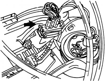
Fig. 216. Position of the Hall sensor connector on the VR6 engine
- disconnect the plug connector (fig. 216, shown by arrow) hall sensor;
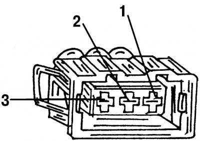
Fig. 217. Checking the Hall sensor on the VR6 engine. "1", "2", "3" - terminal numbers of the plug-in block
- connect a voltmeter to terminal "1" and to terminal "3" (Fig. 217) of the Hall sensor plug. The voltage should be at least 11.5 V;
- if this is not the case, then contact a service station.
2.0 liter engine
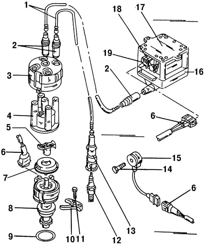
Fig. 210. Elements of the ignition system on a 2.0-liter engine (with Simos injection system): 1 - high voltage wire, to the spark plug; 2 - radio interference suppression plug; 3 - protective cover; 4 - distributor cap; 5 - distributor runner; 6 - three-pin plug connector; 7 - dust cover; 8 - ignition distributor with Hall sensor; 9 - O-ring seal; 10 - pressure bar; 11 - bolt, 25 Nm; 12 - spark plug, 30 Nm; 13 - High voltage wire tip, to spark plug; 14 - bolt, 20 Nm; 15 - knock sensor (G61); 16 - high voltage transformer (N 152); 17 - output stage of high voltage transformer (N157); 18 - terminal "15"; 19 - terminal "1"
- disconnect the plug connector 6 (Fig. 210) from the ignition distributor 8;
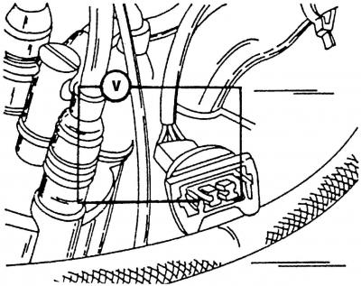
Fig. 218. Checking the Hall sensor on a 2.0-liter engine
- connect a voltmeter between the outer terminals of the plug connector (Fig. 218). The voltage should be at least 10.0 V;
- if this is not the case, then contact a service station.
Checking the knock sensor
Have the knock sensors checked at a service station.
Visitor comments