



2. Connect the multimeter using the wires from VAG 1594 to the outer contacts of the wiring connectors (Fig. 3.44)
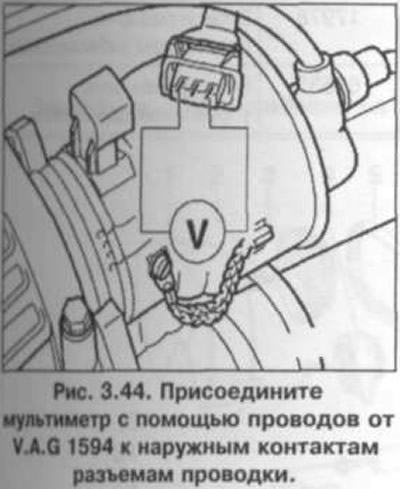
3. Turn on the ignition. Specification value: min. 9 V.
4. Turn off the ignition.
5. Connect the VAG 1598/22 tester to the control unit connector wiring harness (fig. 3.34).
6. Check the wires between the tester and the connector for open circuit: pin 1 + socket 17, pin 2 + socket 13, pin 3 + socket 8. Wire resistance: max. 1.5 ohms.
[The information is available on the website vwmanual.ru]
7. Additionally, check for short circuits between wires.
Specification resistance: ∞ Ohm.
8. If no faults are found in the wiring and there is voltage between contacts 1 and 3, replace the Hall sensor.
9. If no faults are found and there is no voltage between contacts 1 and 3, replace the engine control unit.
Visitor comments