
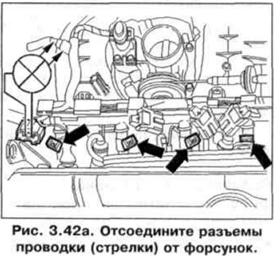
2. Disconnect wiring connectors (arrows) from injectors (pic. 3.42 a).
3. Attach the diode tester VAG 1527 to the pins of the connector of the first cylinder.
4. Try to start the engine with a starter. The tester light should flash.
5. Repeat the same test procedure for injectors 2-4 cylinders. If the tester light does not flash on any of the cylinders, connect a tester to pin 1 and «mass» cylinder #1 (pic. 3.42 b).
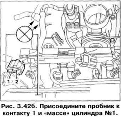
6. Try to start the engine with a starter. The test lamp should light up.
7. If the tester lamp does not light up, check the wires between the contacts of the two-pin wiring connector and the fuel pump relay for an open circuit. Wire resistance: max. 1.5 ohm.
8. If the tester light flashes on one or more cylinders, connect the VAG 1598/18 tester to the engine control unit wiring harness (rice. 3.34). Check the wires between the tester and the injector connectors for an open circuit: cylinder 1 harness connector - pin 2 + socket 7, cylinder 2 harness connector - pin 2 + socket 6, cylinder 3 harness connector - pin 2 + socket 28, cylinder 4 harness connector - pin 2 + socket 4. Wire resistance: max. 1.5 ohm.
9. In addition check up short circuit one on another wires.
Specification resistance: ∞ Ohm.
10. Check wires of pins 1 of injector wiring connectors for open circuit. Wire resistance: max. 1.5 ohm. Additionally, check the short circuit one to the other wires.
Specification resistance: ∞ Ohm.
Testing injector resistance with a wire
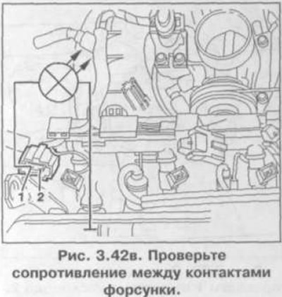
11. Check the resistance between the injector contacts (pic. 3.42 in). Specification resistance: 14-17 ohms.
12. Disconnect the three-pin wiring connector from the ignition coil.
13. Disconnect the four-pin wiring connector from the coolant temperature sensor 2 (pic. 3.42g).
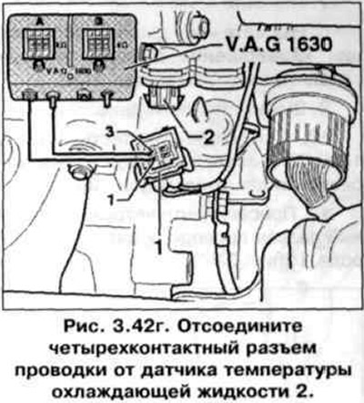
14. Connect the VAG 1630 digital potentiometer using auxiliary wires from VAG 1594 to pins 1 and 3 and set a resistance of 15 kOhm on the connected side.
15. Disconnect the wiring connector from the throttle body, oil pressure sensor and intake manifold pressure sensor, and disconnect the wiring harness from the intake pipe and thermostat housing.
16. Remove the high pressure fuel line assembly with injectors from the intake manifold.
17. Install under the injector to be tested and disconnect the wiring connectors from the injectors (pic. 3.42 d).
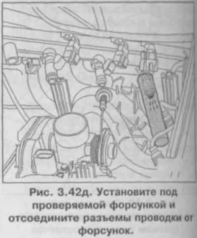
18. Try to start the engine with a starter. The injector should carry out a pulsating injection of fuel.
19. Repeat the procedure for the remaining nozzles. In this case, only the injector to be tested should be connected.
20. Check the tightness of the nozzles. Leakage should be no more than 2 drops per minute.
Attention! When installing injectors, make sure the O-rings are not damaged.
Visitor comments