



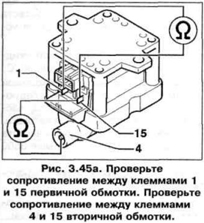
2. Check the resistance between terminals 1 and 15 of the primary winding (fig. 3.45 a). Specification resistance: 0.5-1.5 Ohm. Check the resistance between terminals 4 and 15 of the secondary winding. Specification resistance: 2.5-4 kOhm.
3. If the resistance is not as specified, replace the ignition coil.
4. Disconnect the three-pin wiring connector from the ignition coil.
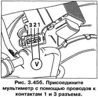
5. Connect the multimeter with wires to pins 1 and 3 of the connector (fig. 3.45 b).
6. Turn on the ignition. Specification value: at least 11 V.
7. If there is no voltage, turn off the ignition.
8. Check the wire between pin 1 of the three-pin harness connector and ground for open circuit. Specification: 1.5 ohms.
9. Check the wire between pin 3 of the three-pin harness connector and the relay panel for open circuit. Specification resistance: 1.5 ohms.
Checking activation
10. Disconnect the wiring connectors from the injectors.
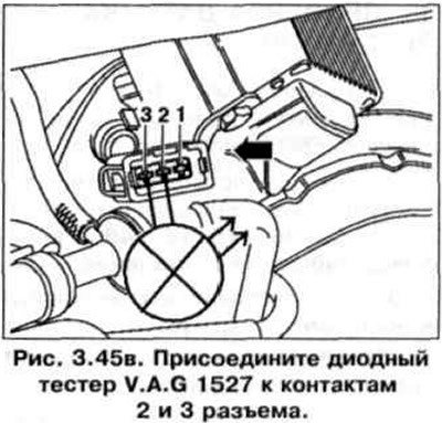
11. Connect the VAG 1527 diode tester to pins 2 and 3 of the connector (fig. 3.45 in).
12. Try to start the engine with the starter and check the ignition signal from the engine control unit. The tester lamp should blink.
13. If the tester light does not flash, connect the VAG 1598/18 tester to the engine control unit wiring harness (fig. 3.34). Check the wires between tester socket 24 and pin 2 of the three-pin harness connector for open circuit. Wire resistance: max. 1.5 ohms.
14. Additionally, check for short circuits between wires.
Specification resistance: ∞ Ohm.
15. If no faults are found in the wiring and there is voltage between terminals 1 and 3, replace the engine control unit.
16. If the voltage is normal and the activation signal is normal, connect the three-pin wiring connector and the high-tension wire to the ignition coil.
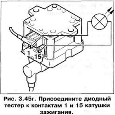
17. Connect the diode tester to terminals 1 and 15 of the ignition coil (fig. 3.45 g).
18. Try to start the engine with the starter and check the ignition signal from the engine control unit. The tester lamp should blink.
Visitor comments