



- disconnect the ground wire from the battery terminal (don't forget about the security code of the radio);
- raise the front of the car and place it on supports;
- remove the sound insulation from the bottom of the engine compartment;
The operating procedure differs for the 2.0-liter engine and for the VR6 engine:
2.0 liter engine
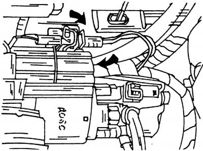
Fig. 337. Black plastic cover and connector of the pull-in relay (2.0 liter engine) shown by arrows
Before disconnecting the wires from the starter, remove the black plastic cover and disconnect the electrical connector of the solenoid relay located underneath (Fig. 337).
[The original can be viewed on the portal VWmanual.ru]
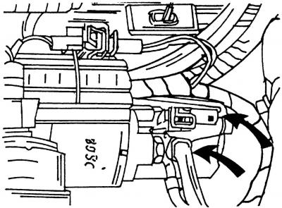
Fig. 338. The location of terminals "30" and "50" on the pull-in relay is shown by arrows
- disconnect the connector (terminal "50") from the pull-in relay and unscrew the nut of terminal "30" (Fig. 338) and bend the wire to the side;
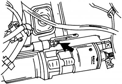
Fig. 339. Under the nut (shown by arrow) the fastening nut is located
- unscrew the nuts and bolts securing the starter. The nut (Fig. 339) is screwed onto the mounting pin;
- remove the starter.
Install the starter in the reverse order of removal, doing the following:
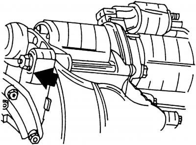
Fig. 340. When installing the starter, tighten the nut shown by the arrow to a torque of 45 N·m
- tighten the starter mounting nut (Fig. 340) to a torque of 45 N·m;
- pay attention to the correct connection of the wires;
- tighten the nut (Fig. 339) (located above the nut already tightened to 45 Nm) to 10 Nm;
- tighten the terminal nut "30" to a torque of 10 Nm;
- connect the battery and enter the security code of the radio and immediately check the operation of the starter.
Removal and installation a starter from a car with a VR6 engine
On a Sharan with a VR6 engine, the starter is removed and installed in the manner described above, however, due to the fact that the starter mount is slightly different, there are the following features:
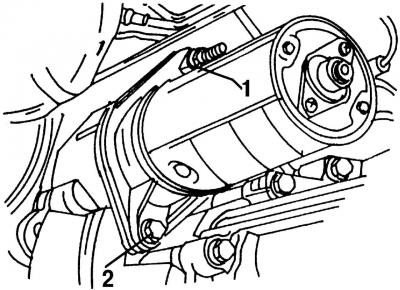
Fig. 341. When installing the starter (vR6 engine with manual transmission) nut 1 and bolt 2 are tightened to a torque of 45 Nm
- the starter is attached to the VR6 engine with a manual transmission using bolt 2 (Fig. 341) and nut 1 (during installation they are tightened to a torque of 45 Nm);
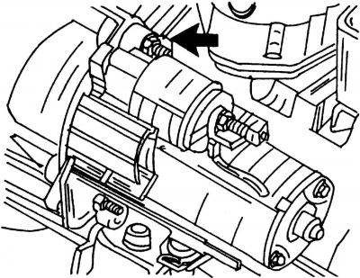
Fig. 342. When installing the starter (vR6 engine with automatic transmission) the nut on the mounting pin is tightened to a torque of 60 Nm
- on the VR6 engine with automatic transmission, the starter is secured with nuts on the mounting pins. When installing the starter, the nut (fig. 342, shown by arrow) tightened to 60 Nm;
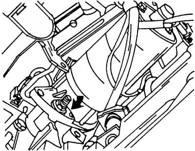
Fig. 343. When installing the starter (vR6 engine with automatic transmission) the lower nut is tightened to a torque of 60 Nm
- tighten the bottom nut (fig. 343, shown by arrow) fastening the starter to the VR6 engine with automatic transmission with a torque of 60 Nm;
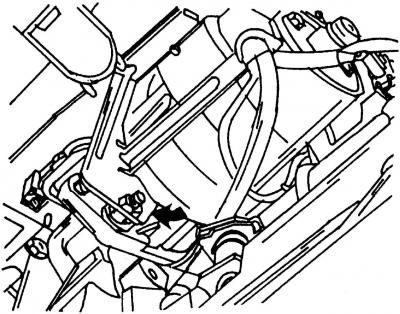
Fig. 344. The wire holder fastening nut is tightened to a torque of 10 Nm
- tighten the nut (arrow, Fig. 344), securing the wire holder with a torque of 10 N·m, and the terminal nut "30" with a torque of 10 N·m.
Visitor comments