
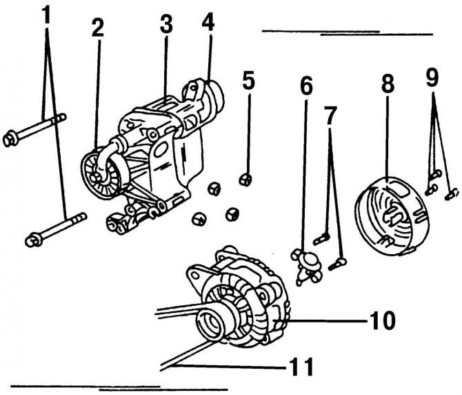
Pic. 334. Details of the generator and its mounting on a 2.0-liter engine: 1 - M8 bolts, 25 Nm; 2 - tension roller; 3 - bracket; 4 - tension device; 5 - nut M8, 30 Nm; 6 - voltage regulator; 7 - voltage regulator mounting bolts, M4; 8 - casing; 9 - casing fastening bolts; 10 - generator; 11 - V-ribbed belt
The design of the generators installed on the 2.0-liter engine and the VR6 engine is shown on (pic. 334) And (pic. 335) respectively.
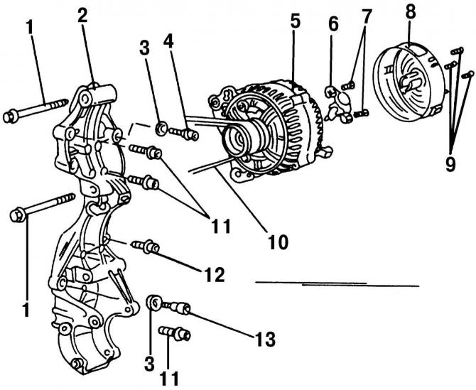
Pic. 335. Details of the generator and its mounting on the VR6 engine: 1 - M8 bolt; 2 - bracket; 3 - washer; 4 - conical bolt, 25 Nm; 5 - generator; 6 - voltage regulator; 7 - voltage regulator mounting bolts, M4; 8 - casing; 9 - casing fastening bolts; 10 - V-ribbed belt; 11 - M8 bolts, 25 Nm; 12 - bolt M8, 25 Nm; 13 - conical bolt, 25 Nm
Withdrawal run the generator in the following order:
- take off «negative» wire from the AB output. Bend the cable away from the AB terminal (to avoid accidental contact);
- remove the drive poly V-belt;
- disconnect the electrical connector from the side of the generator casing and the wire from a separate terminal;
- unscrew the bolts securing the generator to the bracket, remove them and remove the generator.
Installation alternator in the reverse order of removal. Insert the V-ribbed belt into the grooves of the pulleys and adjust its tension.
Visitor comments