



Contents: Checking the resistance of injectors…↓ Checking the spray pattern and…↓ Leak testing ↓ Checking the spray pattern ↓
1. Connect the VAG 1598/26 tester.
2. Connect the VAG 1527 diode tester with a light bulb between sockets 4 (blue) and 2 (red) of the tester to check the supply voltage of the injectors of the 1st and 4th cylinders.
3. Operate the starter. The light on the diode tester should come on.
4. Connect the VAG 1527 diode tester with a light bulb between sockets 13 (blue) and 2 (red) of the tester to check the supply voltage of the injectors of the 2nd and 3rd cylinders.
5. Operate the starter. The light on the diode tester should light up.
6. Turn off the ignition.
7. If the light does not go out, check the power supply voltage of the engine control unit.
8. If the engine control unit supply voltage is normal, replace the engine control unit.
Checking the resistance of injectors and wires
9. Measure the resistance of the injectors using a multimeter (figure 2.84):
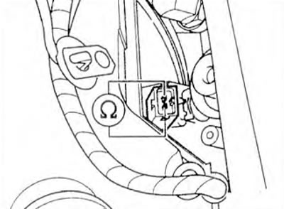
Figure 2.84. Measure the resistance of the injectors using a multimeter.
1st and 4th cylinders between sockets 4 (blue) and 2 (red) of the tester, 2nd and 3rd cylinders between sockets 13 (blue) and 2 (red) of the tester. Specified value: 7-8 Ohm
10. If the specified value is not achieved, remove the throttle control unit and intermediate flange.
11. Measure the resistance between the injector connector contacts. Specified value: 14-16 Ohms. Repeat measurements for injectors of cylinders 2 and 4.
12. If the specified value is not achieved, replace the faulty injector.
13. If the set value is reached. check the wires between the tester and the injector connectors for open circuit using the wiring diagram (figure 2.85).
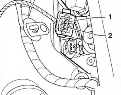
Figure 2.85. Check the wires between the tester and the injector connectors for open circuit using the wiring diagram.
Cylinder 1: Pin 2 and Socket 4 (Blue): Cylinder 2: Pin 2 and Socket 13 (Blue); cylinder 3: contact 2 and socket 13 (blue); cylinder 4: Pin 2 and Socket 4 (Blue). Set Value: Max 1.5 Ohm.
14. Also check the wires for short circuits. Cylinder 1: Pin 2 and socket 13 (blue), Cylinder 2: Pin 2 and socket 4 (blue) Setpoint: ∞ Ohms.
15. Check the wires between the tester and the cylinder connectors for open circuit using the wiring diagram. Cylinder connectors: pin 1 and socket 2 (red). Specified value: max. 1.5 ohms.
16. If the specified value is not achieved, check the wire connections according to the wiring diagram.
17. Disconnect the VAG 1598/26 tester.
Checking the spray pattern and injector leaks
18. Remove the intake manifold with injectors.
19. Install the intake manifold with injectors and connected fuel lines on the VAG 1602 measuring stand (figure 2.86).
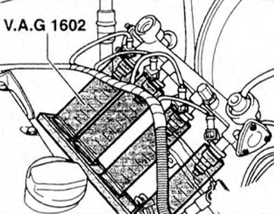
Figure 2.86. Install the intake manifold with injectors and connected fuel lines on the VAG 1602 measuring stand.
20. Connect the wiring connectors to the injectors.
21. Disconnect the red and blue wiring connectors from the engine control unit.
22. Connect the VAG 1348/3A remote control between sockets 10 (red) and 8 (red) of the tester using the VAG 1348/3-2 cable.
Leak testing
23. Operate the VAG 1348/3A remote control for approximately 10 seconds. Check the injectors for leaks. No more than two drops should flow out per minute.
Checking the spray pattern
24. Disconnect the 8-pin wiring connector in the protective sleeve on the block on the battery (figure 2.87).
25. Connect pin 4 to pin 8 (red) of the tester, sockets 4 and 13 (blue) to the negative wire 31 (figure 2.88).
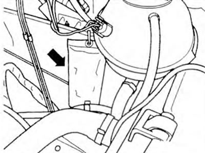
Figure 2.87. Disconnect the 8-pin wiring connector in the protective sleeve on the block on the battery.
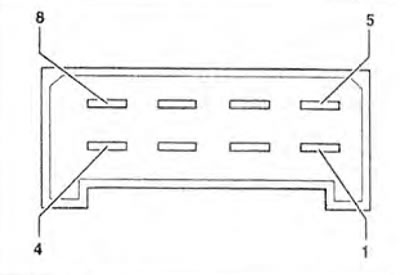
Figure 2.88. Connect contact 4 to contact 8 (red) of the tester, sockets 4 and 13 (blue) to negative wire 31.
26. Operate the VAG 1348/3A remote control. The injectors should have the same spray pattern.
Visitor comments