



Contents: Checking the activation signal…↓ Checking the wires ↓ Checking the primary resistance ↓ Checking the secondary resistance ↓
1. Connect the VAG 1598/26 tester.
2. Connect the multimeter to jack 2 (red) of the tester to measure voltage.
3. Turn on the ignition. Set value: at least 11.0 V.
4. If the specified value is not reached, check the supply voltage of the Motronic control unit.
5. If the specified value is reached, check the transformer wires.
Checking the activation signal (terminal 1)
6. Connect the VAG 1598/26 tester.
7. Connect the VAG 1527 diode tester between sockets 10 (blue) and 2 (red) of the tester to check the activation signal for the transformer of the 1st and 4th cylinders.
8. Operate the starter. The light on the diode tester should light up.
9. Connect the VAG 1527 diode tester between sockets 11 (blue) and 2 (red) of the tester to check the activation signal for the transformer of the 2nd and 3rd cylinders.
10. Operate the starter. The light on the diode tester should come on.
11. Turn off the ignition.
12. If the light does not come on, check the supply voltage of the Motronic control unit.
13. If no fault is found in the supply voltage to the Motronic control unit, replace the Motronic control unit.
14. If the light comes on, check the transformer wires.
Checking the wires
15. Remove the ignition system cover.
16. Disconnect the 2-pin connectors from the transformers (arrows) (figure 2.93)
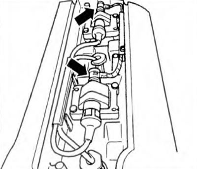
Figure 2.93. Disconnect the 2-pin connectors from the transformers (arrows).
(The text is copied from this portal: VWmanual.ru)
17. Check the wires between the 2-pin connectors and pin 1 (red) of the tester for open circuit (figure 2.94). Wire resistance: max 1.5 ohm.
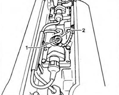
Figure 2.94. Check the wires between the 2-pin connectors and pin 1 (red) of the tester for open circuit.
18. Check the wire between the tester and the 2-pin connector of the 1st and 4th cylinder transformer for an open circuit using the wiring diagram (figure 2.95): contact 2 and socket 10 (blue). Wire resistance: max. 1.5 ohms.
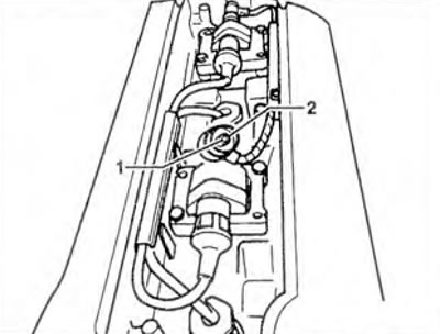
Figure 2.95. Check the wire between the tester and the 2-pin connector of the 1st and 4th cylinder transformer for an open circuit using the wiring diagram.
19. Check the wire between the tester and the 2-pin connector of the 2nd and 3rd cylinder transformer for an open circuit, using the wiring diagram (Fig. 2.95): contact 2 and socket 11 (blue). Wire resistance: max. 1.5 Ohm.
20. Also check the wires for short circuits between themselves: connector of the transformer of the 1st and 4th cylinders - contact 1 and socket 10 (blue), connector of the transformer of the 2nd and 3rd cylinders - contact 1 and socket 11 (blue), contact 2 of the connector of the transformer of the 1st and 4th cylinders and contact 2 of the connector of the transformer of the 2nd and 3rd cylinders. Set value: ∞ Ohm.
21. If the specified value is not achieved, check the wire connections according to the wiring diagram.
22. After checking the wires, disconnect the VAG 1598/26 tester.
Checking the primary resistance
23. Check the primary resistance of both transformers between terminals 4 and 15 using a multimeter (figure 2.96). Set value: 0.3-0.8 Ohm.
24. If the specified value is not achieved, replace the transformer.
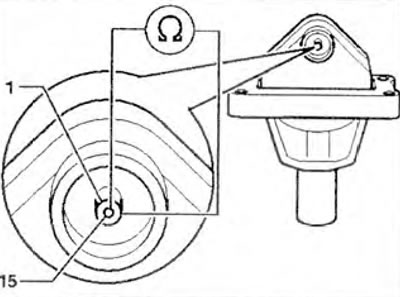
Figure 2.96. Check the primary resistance of both transformers between terminals 4 and 15 using a multimeter.
Checking the secondary resistance
25. Check the secondary resistance of both transformers between terminals 4a and 4b using a multimeter (figure 2.97). Set value: 5.2-8.5 kOhm.
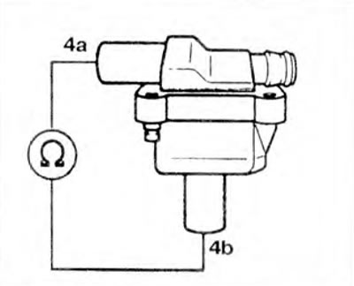
Figure 2.97. Check the secondary resistance of both transformers between terminals 4a and 4b using a multimeter.
26. If the specified value is not achieved, replace the transformer
Visitor comments