



2. Disconnect the 4-pin connector from the oxygen sensor (arrow) (figure 2.77).
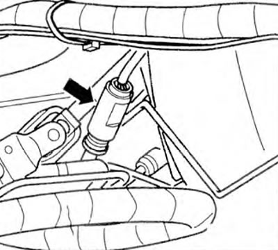
Figure 2.77. Disconnect the 4-pin connector from the oxygen sensor (arrow).
3. Check the wires between the tester and the 4-pin connector for open circuit: pin 3 and socket 7 (red), pin 4 and socket 6 (red) (figure 2.78). Wire resistance: max 1.5 ohm.
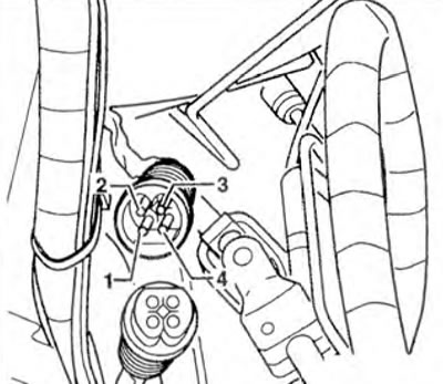
Figure 2.78. Check the wires between the tester and the 4-pin connector for an open circuit.
4. Also check the wires for short circuits: pin 1 and socket 6 (red), pin 1 and socket 7 (red), pin 2 and socket 6 (red), pin 2 and socket 7 (red), pin 3 and socket 6 (red). Specified value: ∞ Ohms.
5. If the set value is not achieved, check the wires using the wiring diagram.
6. If no faults are found, replace the oxygen sensor.
7. Disconnect the VAG 1598/26 tester.
Visitor comments