



2. Remove the timing belt guard from the fuel pump.
3. Set the piston of the 1st cylinder to TDC.
4. Align the marks on the gear and fuel pump housing with the marks on the flywheel and clutch housing (figure 1.12).
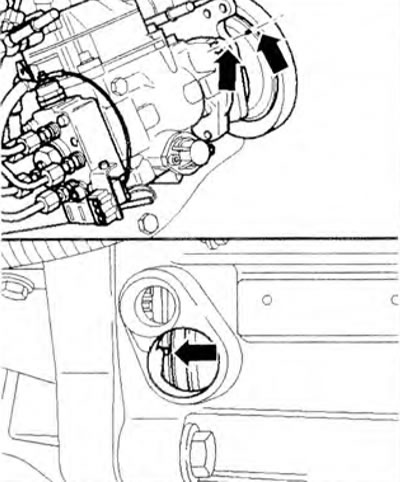
Figure 1.12. Align the marks on the gear and fuel pump housing with the marks on the flywheel and clutch housing.
5. Align the marks on the pulley (damper) and the bottom of the casing (arrows) (figure 1.13).
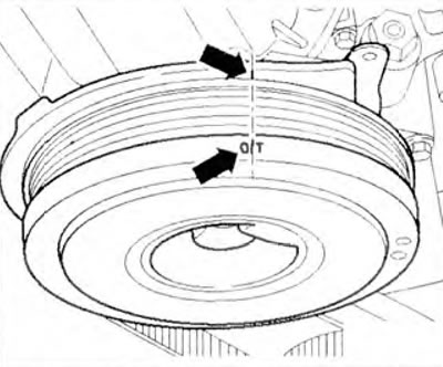
Figure 1.13. Align the marks on the pulley (damper) and the bottom of the casing (arrows).
6. Secure the camshaft pulley using support 3036. Loosen the mounting bolt and remove the toothed pulley.
7. Remove the plug and screw in the adapter 3313 with a pointer indicator (measurement range 0-3 mm) with a preload of approximately 2.0 mm (figure 1.14).
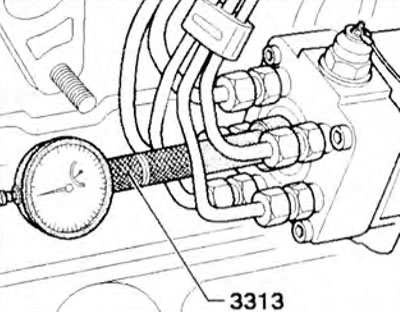
Figure 1.14. Remove the plug and screw in the adapter 3313 with the pointer indicator.
8. Check that the marks on the gear and the fuel pump housing (arrows) match (figure 1.12).
9. Unscrew the locking bolt 2 on the fuel pump and remove the intermediate plate 1 underneath it (figure 1.15).
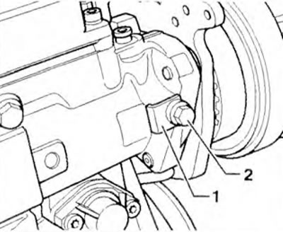
Figure 1.15. Unscrew the locking bolt 2 on the fuel pump and remove the intermediate plate 1 underneath it.
10. Set the indicator arrow to "0".
11. After making sure that the fuel pump piston is in the BDC position, slowly rotate the caliper 3036 in the direction of crankshaft rotation (clockwise).
12. The indicator arrow should be set to "0"; if necessary, set the arrow to "0" after setting the piston to the BDC position.
13. On AGX engines up to C 1.99: slowly rotate the fuel pump pulley in the direction of crankshaft rotation (clockwise) using the 3036 caliper until the indicator shows a lift value of 0.35 mm.
14. On the AGX engine from 02.99. AHD. ANJ, ARA: slowly rotate the fuel pump pulley in the direction of crankshaft rotation (clockwise) using the 3036 caliper until the indicator shows a lift value of 0.55 mm.
15. Tighten the fuel pump locking bolt 2 (30 Nm).
16. Check the alignment of the TDC mark on the flywheel and clutch housing.
17. Install the timing belt on the fuel pump pulley. Tighten the lock bolt so that the pulley can be rotated by hand. If the belt was previously installed, install it in the direction of its previous rotation.
18. Check the position of the guide roller. Pointer 1 of the guide roller must be aligned with the mark on the cylinder head flange (arrow) (figure 1.16). If necessary, loosen bolt 2 and adjust the position of guide roller 1. Tighten the guide roller bolt to 20 Nm.
[The original can be found at: www.VWManual.ru]
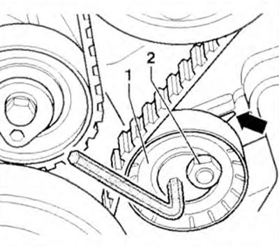
Figure 1.16. Check the position of the guide roller. Pointer 1 of the guide roller must align with the mark on the cylinder head flange (arrow). If necessary, loosen bolt 2 and adjust the position of guide roller 1.
19. Install tension roller 1 and adjust it so that the eye of the tension roller fits into the groove on the console (arrow B) (figure 1.17). Tighten the bolt by hand. Rotate the tension roller counterclockwise until. until it stops. Then rotate it in the opposite direction until the marks (arrow A) align. Tighten the bolt to 15 Nm.
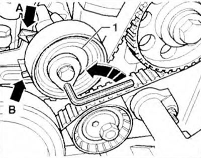
Figure 1.17. Install tension roller 1 and adjust it so that the eye of the tension roller fits into the groove on the console (arrow B). Rotate the tension roller counterclockwise until it stops.
Then rotate it in the opposite direction until the marks (arrow A) align.
20. Lock the fuel pump pulley with caliper 3036 and tighten to 160 Nm.
21. Unscrew the locking bolt 2 and install the intermediate plate 1 (figure 1.15). Tighten the bolt to 25 Nm.
22. Remove the dial indicator and screw in the plug. Check the fuel injection start and adjust it if necessary.
23. Install the service cover.
Visitor comments