



Contents: Upper part of the carburetor body ↓ Lower part of the carburetor body ↓ Carburetor characteristics ↓
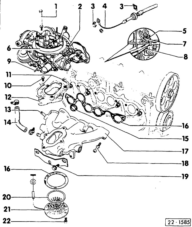
- 1 — bolt, 7 Nm
- 2 — nipple for connecting the fuel supply line
- 3 - safety bracket
- 4 - gas thrust
- 5 — temperature indicator sensor
- 6 — carburetor 2EZ
- 7 — thermal switch of the automatic device for enriching the combustible mixture at start-up
Identification feature: green insulation.
- 8 — thermal switch of the intake air heater
With red insulation.
- 9 — nipple
To connect the temperature regulator in the air filter. y - bolt, 13 Nm
- 11 - lock washer
- 12 — flange
- 13 — to the brake booster
- 14 - to the automatic device for enriching the combustible mixture during start-up
- 15 - sealing ring
Replace if damaged.
- 16 - sealing gasket
Always replace.
- 17 — intake manifold
- 18 — bolt, 25 Nm
- 19 — bolt, 20 Nm
- 20 — sealing ring
Always replace
- 21 — intake manifold heater
- 22 — bolt, 10 Nm
Upper part of the carburetor body
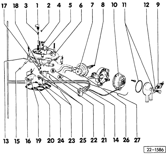
- 1 - ventilation system tube
- 2 - air jet of the main metering system, chamber 1
- 3 — idling system air jet
- 4 - metal flame extinguishing mesh
- 5 — economizer tube
- 6 - upper part of the carburetor
- 7 - adjusting screw, chamber 1
- 8 - adjusting screw, chamber 2
- 9 - thermopneumostatic valve
To control the vacuum ignition timing regulator.
- 10 — air damper position control device
- 11 — sealing ring
- 12 — bolt, 10 Nm
- 13 — float axis
- 14 - to the time-delay thermal valve (B)
- 15 — grid
- 16 - float needle
- 17 - main jet, chamber 1
- 18 - main jet, chamber 2
- 19 — float
- 20 - sealing gasket
Replace, pay attention to execution.
- 21 - to the bottom of the carburetor (A)
- 22 - atomizer, chamber 2
- 23 — wedge lock
- 24 - atomizer, chamber 1
- 25 - sealing gasket
Replace, do not swap.
- 26 — vacuum limiter (Pulldown)
- 27 - automatic device for enriching the combustible mixture at start-up
Lower part of the carburetor body
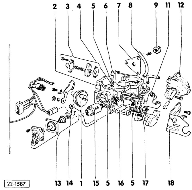
- 1 - time delay thermal valve
- 2 - lower part of the carburetor body
- 3 - economizer valve for operation at partial loads
Always replace after removal.
- 4 — grid
- 5 - sealing ring
- 6 - injection tube
- 7 — bracket
For thermal switch.
- 8 - to the temperature controller
The temperature regulator is located in the air filter housing.
- 9 - thermal switch
For additional fan activation.
- 11 — cold engine idle speed adjustment screw
- 12 — vacuum throttle position regulator, chamber 2
- 13 - accelerator pump
- 14 - to the upper part of the carburetor body (A)
- 15 — fuel shut-off valve
- 16 — idle speed adjustment screw
With guide tube.
- 17 — CO content adjustment screw
- 18 - counter support
Carburetor characteristics
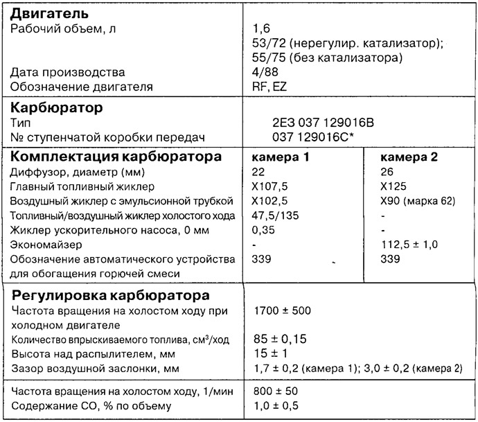
*) Since 5/88; with end damper for throttle valve.
Visitor comments