



The door is installed correctly if, after closing, its gaps relative to adjacent body parts are parallel, and the door itself does not protrude or sink, its outline matches the outline of adjacent parts.
A depression of the rear side door relative to the front door by approximately 1 mm is acceptable.
Gap width. Golf cars:
- The gap between the front door and the front wing is 3.5±0.5 mm
- Gap between front door and rear wing (two-door cars) — 3.5±0.5 mm
- The gap between the front and rear doors is 4.2±0.5 mm
- The gap between the rear door and the rear wing is 3.5±0.5 mm
- The gap between the door and the threshold is 4.5±0.5 mm
If the specified nominal dimensions are not maintained, then the lock bracket should be removed from the body and the door hinge mounting bolts should be loosened.
2. Loosen bolts 5 of the upper hinge and bolts 1 and 2 of the lower door hinge (see illustrations).
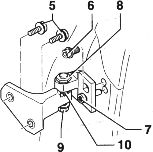
58.2. Fastening the upper door hinge
5 - bolts. Tightening torque 20 Nm + 90° turn
6 - bolt. Tightening torque 20 Nm + 90° turn
7 - guide pin. Tightening torque 10 Nm
8 - Hexagon head eccentric adjusting screw
9 - lock nut Tightening torque 28 Nm
10 - emphasis
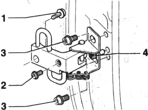
58.2a. Fastening the lower door hinge
1 - bolt. Tightening torque 20 Nm + 90° turn
2 - bolt. Tightening torque 20 Nm + 90° turn. Only accessible from the showroom
3 - bolt. Tightening torque 20 Nm + 90° turn
4 - guide pin. Tightening torque 10 Nm
Caution! To ensure access to bolt 2 (see illustration 58.2) first, you need to remove the lower part of the trim on the front pillar or on the center pillar if you are removing the rear side door.
Attention! The bolts are self-locking and must be replaced with new ones after each dismantling. The exception is the guide pins.
3. Fit the door by moving it forward or backward on the hinges.
Warning! Trying to move the door up is useless because the door will immediately move down.
4. Loosen bolts 3 and 6, as well as guide pins 4 and 7, to fit the door to the contour and fit the door (see illustrations 58.2 and 58.2a).
Attention! If the door fit needs to be adjusted only slightly, it is enough to loosen the lock nut 9 on the upper door hinge, and then turn the eccentric bolt 8 by the hex head in the desired direction (see illustration 58.2).
5. After adjustment, tighten the hinge bolts to 20 Nm and then tighten them further with a wrench by 1/4 turn (90°).
Tighten guide pins 4 and 7 to 10 Nm (see illustrations 58.2 and 58.2a).
6. Replace and secure the lock bracket 1 with bolts, tightening the bolts by hand until the bracket can be moved only by applying sufficient force (see arrows in the illustration).
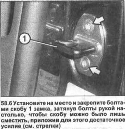
7. Close the door. The bracket will move and take the desired position. After this, carefully open the door and tighten the bolts with a force of 20 Nm.
Visitor comments