



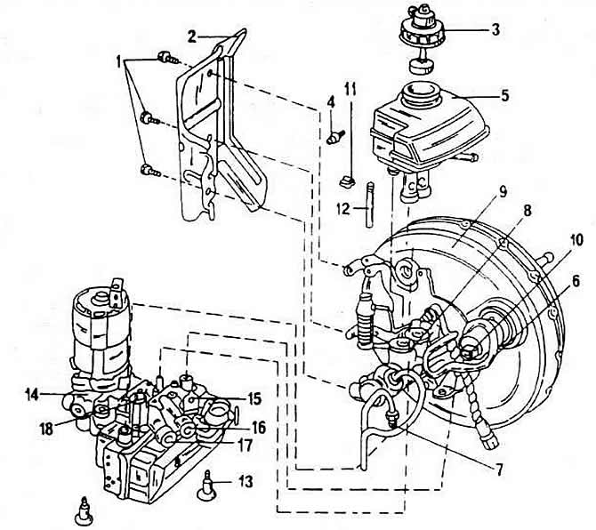
1 - screws
2 - protective shield
3 - reservoir cap
4 - screws
5 - reservoir
6, 7 - brake line
8 - master brake cylinder
9 - brake booster
10 - brake pedal position sensor
11 - locking clamp
12 - connecting pin
13 - screws
14 - hydraulic control device
15 - connecting element of the brake line from the hydraulic control device to the left front brake seat
16 - connecting element of the brake line from the hydraulic control device to the right rear brake cylinder
17 - connecting element of the brake line from the hydraulic control device to the left rear cylinder
18 - connecting element of the brake line from the hydraulic control device to the right front brake seat.
The braking connection element of the line 6 connects the braking circuit, controlled by the pusher lever, with the hydraulic control device.
(The information is presented on the website: VWMANUAL.ru)
The connecting element of the braking line 7 connects the intermediate braking circuit (intermediate piston controlled braking circuit) with hydraulic control device.
The brake line connecting element 15 connects the hydraulic control device to the left front brake seat.
The brake line connecting element 16 connects the hydraulic control device to the right rear wheel brake cylinder or the brake saddle cylinder.
The brake line connection element 17 connects the hydraulic control device to the left rear wheel brake cylinder or the brake saddle cylinder.
The brake line connecting element 18 connects the hydraulic control device to the right brake seat.
The cap 6 of the reservoir is equipped with a signal device of the anti-lock device, i.e. the plug is located in the cap 3.
When dismantling the reservoir, it is necessary to replace the reservoir sealing nozzles. When installing, lubricate the nozzles with brake fluid.
The hydraulic device cannot be repaired.
The electronic control unit for the anti-lock braking system is located under the floor covering in front of the front seat next to the driver's seat.
Visitor comments