
Separately located in the engine compartment, the expansion tank is connected by one pipe to the radiator with the other to the heater and coolant pump. A coolant level sensor is located in the expansion tank, which is connected to the indicator lamp on the instrument panel.
The expansion tank is equipped with a filler neck with a cap (the radiator does not). The layout of the cooling system is shown in fig. 228 and 229.
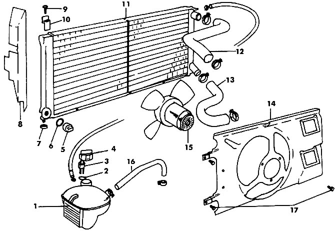
Pic. 228. The device of the engine cooling system (coolant pump and thermostat not shown): 1 - expansion tank; 2 - gasket; 3 - coolant sensor; 4 - cover; 5 - thermal switch; 6 - gasket; 7 - rubber bushing; 8 - casing; 9 - bolt (10 Nm); 10 - bracket; 11 - radiator; 12 - upper branch pipe; 13 - lower branch pipe; 14 - fan casing; 15 - fan motor; 16 - return pipe; 17 - bolt (10 Nm)
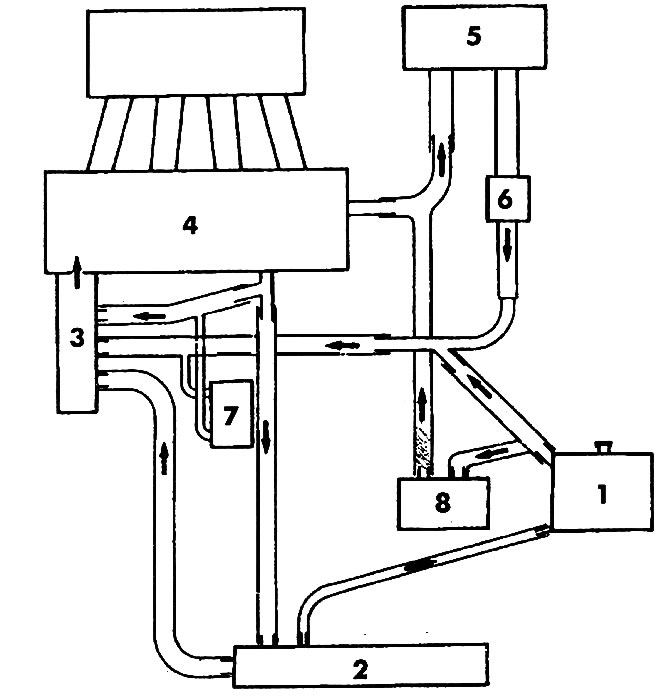
Pic. 229. Scheme of the cooling system (motors JP, ME, JR, 1V): 1 - expansion tank; 2 - radiator; 3 - coolant pump with thermostat; 4 - head of the engine block; 5 - heater; 6 - heater valve; 7 - oil cooler (only on vehicles with automatic transmission and turbo diesel engine JR, 1V); 8 - gearbox oil cooler (only on vehicles with automatic transmission and turbo diesel engine JR, 1V)
Visitor comments