
Depending on the model, two types of towbars are used - one for the Golf model from 1974 to the beginning of 1984 (except for a convertible) and Scirocco from 1974 to 1981, the other for the pre-1983 Jetta model. Installation instructions are below.
Jetta (pic. From:15)
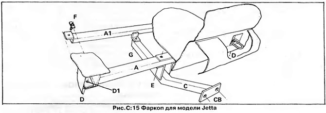
1. Remove the rear bumper (see chapter "Body and body equipment") and lift the boot floor cover in the spare wheel well.
2. Insert two plates with bolts (F) inside the side members of the body through the existing holes and freely, without tightening the bolts, fix the front cross member (A1). To ensure an even fit of the plates, remove the mastic in the places of their installation.
3. Attach the rear cross member (A) to the longitudinal beam (WITH) at the point (E). Place the assembled beams under the vehicle and attach the stringer to the front cross member at the point (G).
4. Position the rear cross member exactly in the center of the vehicle and drill at the points (D) two holes with a diameter of 11.2 mm (7/16 inch). The right rear bolt is inserted through the towing eye reinforcement plate, and a separate plate must be placed under the left bolt head (D1). Fasten the entire structure with the bolts provided and tighten them securely.
5. Fasten the ball pin and the electrical connector mounting bracket to the end of the towbar stringer (sockets). Connect the wires to the outlet (s) as described in this section below.
Golf and Scirocco (pic. From:16)
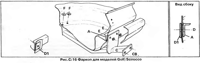
1. Remove the rear bumper (see chapter "Body and body equipment"), raise the floor covering in the luggage compartment and remove the spare wheel.
2. Attach the crossbar (A) to the back panel so that its lower edge rests on the floor; so that the cross member fits snugly, remove the mastic from the floor. At points (D) drill two holes with a diameter of 9.6 mm along the edges of the crossbar (3/8"). Attach the cross member to the rear panel by placing reinforcing plates under the bolt heads from the outside (D1). Drill two center holes at points (E) diameter 11.2 mm (7/16 inch).
3. Loosely attach the stringer (WITH) bolted at points (E). Position the beam in the center of the car and drill two holes with a diameter of 9.6 mm (3/8") at points (F) in front of the spare wheel well. Fasten the stringer (WITH) at points (F) supplied bolts by placing large flat washers under the bolt heads.
4. Tighten all bolts, attach the ball pin and electrical outlet bracket to the stringer. Connect the wires to the outlet (s) as described in this section below.
NOTE: Retighten all bolts after 80 km with a trailer.
Towbar electrical equipment
After installing the towbar, you must install the electrical connector (socket) for connecting the trailer to the vehicle's electrical system.
Below are the installation instructions for the Hella Transflash electrical kit (pic. C:17).
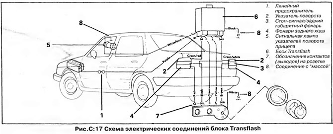
When installing this kit, it is not necessary to install a high power turn signal breaker relay, as the kit includes "secondary" a breaker that controls the alarm and direction indicators on the trailer.
The kit also includes an additional electrical connector (socket), with sockets for connection (charging) auxiliary battery, caravan refrigerator power supply, reversing light and indicator light on the instrument panel.
1. Transflash relays should be mounted with pins down. Install the relay at the rear of the vehicle, in the trunk near the wiring harness. Position the relay so that it cannot be damaged by accidentally shifting luggage.
2. Install a lamp on the dashboard that indicates the operation of the direction indicators or the burnout of one of the lamps. Mark the location of the trailer warning light so that it is clearly visible from the driver's seat and compatible with other instruments. If necessary, install an additional bracket for the lamp under the dashboard.
3. Make sure the direction indicators and lights are working properly. Eliminate faults before proceeding further. Disconnect the battery.
4. From one end of the stranded cable, strip 50 mm of the outer black insulation, being careful not to damage the insulation of the cable wires.
5. Strip 16 mm of insulation from the ends of each cable wire. Twist the strands of each wire together.
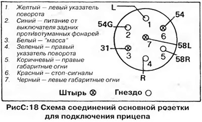
6. Connect the wires to the outlet pins according to their color. Contact numbers are indicated on the socket housing (pic. From:18). Make sure that each wire is securely connected to the outlet pin and that the strands of the wires do not short-circuit adjacent pins.
7. Remove a short section of outer insulation from the free end of the cable. Grab the bundle of wires with pliers and, holding the outer insulation with your other hand, slide it to the outlet as close as possible, rubbing the insulation with your hand with force.
8. Insert the cable into the rubber grommet and slide the grommet over the cable all the way to the receptacle flange.
9. Pass the cable through the center hole of the receptacle mounting bracket. When connecting the socket to the bracket, the end of the outer cable insulation must pass through the hole in the bracket to protect the wires from chafing. Secure the outlet to the bracket using the three supplied bolts, nuts and washer. The hinge of the socket cover must be on top.
10. Install the outlet mounting bracket on the vehicle between the towbar stringer and the ball pin. Pass the end of the cable into the trunk through any available hole, or specially drill a 13mm diameter hole behind the bumper.
11. Insert the rubber grommet into the hole and pull the cable through it. If the cable is difficult to pass through the grommet, lubricate it Carefully pull the cable into the trunk to take up any slack. Wrap electrical tape around the rubber grommets to prevent sagging. Carefully remove all outer insulation from the cable section inside the vehicle, leaving a 26mm piece of insulation protruding from the rubber grommet.
12. Connect the wires to the Transflash box as described below:

See wire location and color on "Wiring diagrams". When connecting the rear fog lamps, cut their wire and connect the cut end from the switch to the blue wire of the cable going to pin 2 (54G) sockets Using the supplied red-brown wire, connect terminal 58b of the socket to the remaining cut end of the wire going to the rear fog lights of the car.
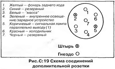
Additional outlet
Install an additional socket if necessary (this will require a double bracket for mounting sockets). Connect the wiring harness to the outlet as shown in fig. From:19. The spare pins of the socket can be used as you wish, but the current through each pin must not exceed 16 A.
Checking work
1. Check all connections, then connect the wires to the battery. Be aware that if the breaker wiring or rear lighting wiring is incorrectly connected, the breaker may be damaged due to a short circuit.
2. Trailer wiring must be connected to the 7-pin plug according to the diagram (pic. From:18).
3. Connect the trailer to the vehicle and plug the trailer's socket into the vehicle's socket.
4. Turn on the parking lights of the car. The side lights of the vehicle and trailer, as well as the license plate lights on both vehicles, should light up.
5. Turn on the ignition and press the brake pedal. The brake lights of the car and trailer should come on at the same time.
6. Turn on the left turn signal. All left direction indicators on the vehicle and on the trailer must flash together. In addition, the trailer's direction indicator light should flash alternately with the vehicle's turn signal light. Repeat the test for the right direction indicators.
7. Disconnect the trailer connector and turn on the left direction indicators on the vehicle. The additional signal lamp should not light up. Make sure the direction indicators on the car are working correctly, repeat the test for the right indicators.
Visitor comments