
A sliding door is installed correctly if, when closed, it is everywhere at the same distance from the doorway.
The embossed belt line of the door must correspond to the same line of the body. In addition, you need to pay attention to the fact that the door does not stand too outward or inward. To meet these requirements, you need to carry out the following work.
Lower Roller Guide Adjustment
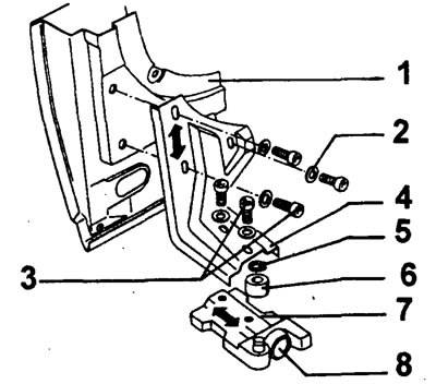
(1) sliding door
(2) washer
(3) cylindrical bolt M8x18, tightening torque 21-25 Nm
(4) roller guide bracket
(5) retaining ring
(6) bottom drive rollers
(7) bottom roller guide
If the door is not height-adjusted, the roller guide bracket must be moved.
If the door does not align in front, the lower roller guide must be moved.
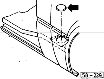
(58-229) push out the plastic valve from below with your finger.
Loosen both bolts of the lower roller guide (see fig. 58-228), press the roller guide as far as it will go against the door and screw only the bolt on the door side.
Close the door carefully.
Gradually loosen the bolt on the door side. An assistant should watch from outside when the door matches. Then tighten the bolt again.
Open the door and tighten both bolts to the torque shown in fig. 58-228.
Top Roller Guide Adjustment
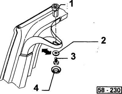
(1) upper roller guide
(2) washer
(3) hex bolt M8x15, tightening torque 21-25 Nm
(4) cap
If the door does not align at the front at the top, then remove the cap by hand and move the pin with the roller guide.
Adjustment of a bolt with a pin and door hinges
The door is not set in height.
Unequal front and rear door clearances.
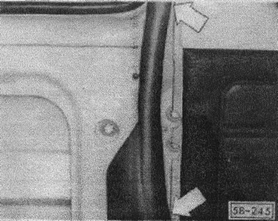
(58-245) open the door and remove the stroke from the rack.
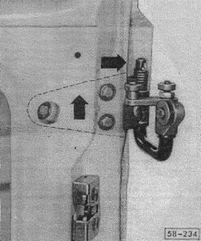
(58-234) before each adjustment or installation of the pin with a pin, the bolts of the articulated device must be loosened, the device should be moved to the highest, most rear position and screwed with three screws.
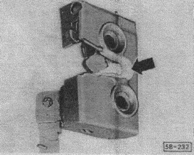
(58-232) for the correct adjustment of the bolt relative to the mouth of the lock, the lock must have a plastic bracket.
New replacement locks have this shackle and can be ordered separately.
Equip the lock with a spacer bracket.
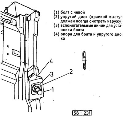
Screw the bolt 1 and the elastic disk 2 to the support 4. In this case, the elastic disk should sit in the center relative to the setting lines 3. This is the main setting of the bolt with the pin.
Carefully move the door back, slightly lifting it in the groove area of the relief line.
Check the height of the door and measure possible correction values.
Open the door and mark the correction value on the bolt support with a felt-tip pen.
Bring the bolt to the marked position.
Close the door carefully again (assistant is inside) and again check the position of the door in the doorway.
If the door is correctly positioned in terms of height and correspondence of the embossed belt line, completely loosen the bolts of the hinged device.
Straighten the door longitudinally from the outside with plastic wedges.
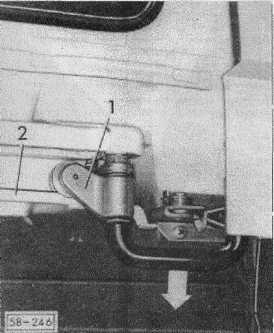
(58-246) Lower the roller trolley 1 with the shackle of the swivel device so that the carrier roller sits on the guide screw 2.
Tighten the bolts of the hinge device from the inside, open the door and remove the spacer bracket from the lock.
Tighten all bolts in compliance with the tightening torque: bolts of the articulated device - 21-25 Nm, bolt with a pin - 45-55 Nm.
Slide the stroke onto the edge of the rack.
Swivel Adjustment Only
Unequal front and rear door clearances.
If repositioning of the pin bolt is not required, the swivel device can be adjusted separately.

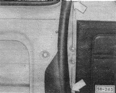
(58-245) open the door and remove the stroke.
Remove the hinged door from the middle guide rail, see illustration. "Dismantling and installation of a sliding door".
Loosen the swivel bolts.
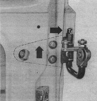
(58-234) move the swivel device to the highest, rear position and fasten the three hex bolts.
Reinsert the door together with the hinged device into the middle guide rail.
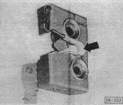
(58-232) press a plastic spacer into the mouth of the lock.
Carefully move the door back, slightly lifting it in the area of the relief line (assistant is on the bus).
Loosen the bolts of the swivel device from the inside.
Check the front and rear door gaps, if necessary align them with plastic wedges.
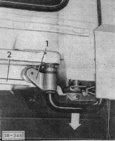
(58-246) lower the roller trolley 1 with the swivel bracket so that the carrier roller sits on the guide rail 2.
Tighten the swivel device bolts from the inside to 2125 Nm.
Open the door and remove the spacer bracket from the lock, slide the stroke onto the edge of the rack.
Visitor comments