



Contents: Dismantling ↓ Installation ↓
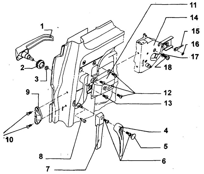
(1) External door handle
(2) socket
(3) spacer washer
(4) interior door handle (for a van)
(5) cap
(6) screw M5x15*
(7) interior door handle (for the bus)
(8) safety button
(9) thrust plate
(TO) countersunk head screw M8x16
(11) mounting plate
(12) countersunk head screw M6x14
(13) countersunk head screw M6x14 (lock fastening)
(14) Remote controlled lock
(15) wire traction
(16) lock washer
(17) washer
(18) countersunk head screw M5x10* (external door handle mounting)
* The indicated screws must be secured with liquid one-component substance type 274, blue.
Dismantling
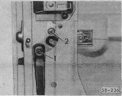
(58-236) Unscrew bolts 1 and 2 from the inner and outer door handles.
Remove the handles together with the spacer washers.
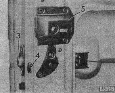
(58-237) unscrew the stop plate 3. unscrew the safety button 4. unscrew the mounting plate 5.
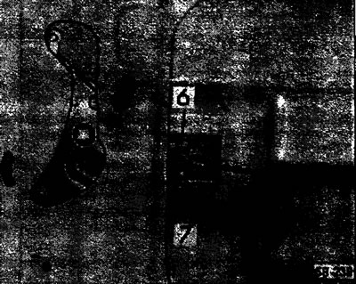
(58-238) Separate the lock washer from the wire rod and lock.
Unscrew the bolt (arrow) and remove the lock from the space between the outer and inner sheet metal sheathing.
Installation
Slide the lock between the outer and inner trim, lightly screw on the stop plate.
Coat the screws of the inner and outer door handles with a one-component substance (see fig. 58-235) and screw on both handles
Tighten the bolts securing the lock.
Screw in the safety button.
Observe the tightening torques of the bolts, see Fig. 58-235.
Visitor comments