
Removal and installation of lining from the side of the threshold
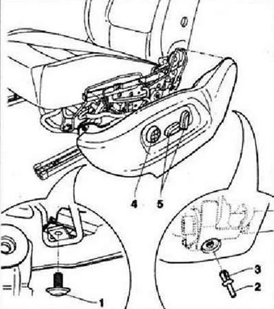
Switch off the ignition. Remove screw -1- (2 Nm). Press expansion pin -2- out of expansion piston -3- and remove the piston. Detach the trim from the seat towards the outside. Disconnect wiring harness from driver's seat lumbar support adjustment switch -E176- -4- and from driver's seat adjustment control panel -E470- -5-. Disconnect wiring harness from trim.
Removal and installation of switches
The following switches are fitted in the trim on the sill side: Driver's seat lumbar support adjustment switch -E176-, Driver's seat position control panel -E470-.
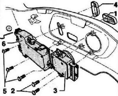
Switch off the ignition. Remove trim from sill side. Using puller -T10236-, carefully remove button -1- from lumbar support adjustment switch -3-. Remove screws -2- (1 Nm) and remove the lumbar support adjustment switch -3- from the trim. Using puller -T10236-, carefully remove button -4- from seat control panel -6-. Remove three screws -5- (1 Nm) and remove the seat position control panel -6- from the trim.
Removal and installation of an arm of facing from a threshold
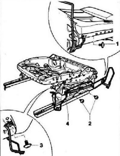
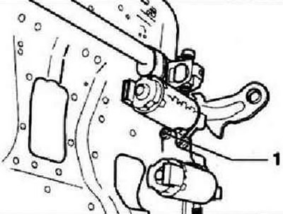
Remove trim from sill side. Detach trim in area of screw -1- and lift cushion slightly. Remove screw -1- (8 Nm). Remove screw -2- (8 Nm). Remove two screws -3- (8 Nm). Remove bracket -4- from seat frame.
Removal and installation of the mechanism for adjusting the longitudinal position of the seat
Note: The electric motor for adjusting the longitudinal position of the seat cannot be replaced separately. It comes with the lower seat frame.
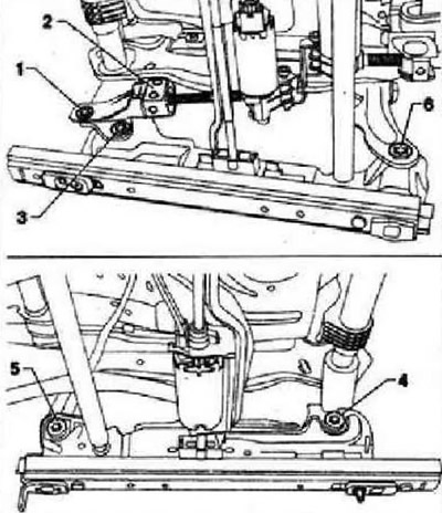
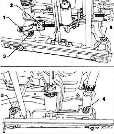
Remove head restraint. Move the seat up as far as possible. Position seat repair bracket -VAS 6136- on stand -VAS 6095-. Remove the front seat. Attach seat to bracket -VAS 6136-. Remove the front seat belt buckle. Remove lining from tunnel side. Remove trim from sill side. Remove the wiring harnesses from the lower seat frame. Remove trim bracket from sill side. Disconnect the harness from the seat fore and aft motor. Remove screw -1- for height adjustment from seat frame on sill side. Secure socket for spindle -2- against rotation. Remove screws -5- and -6- at front. Remove screws -3- and -4- at rear.
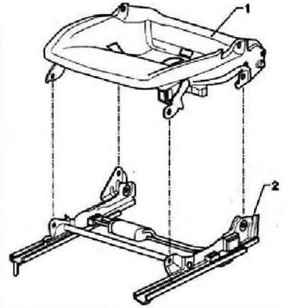
Remove the seat base -1- from the bottom frame of the seat -2- towards the top.
Installation
Insert seat cushion base -1- into lower frame -2-.
Instructions: The threads of the new screws are coated with microcapsules with a fixative, so the screws must be replaced after each unscrewing. Before installing new screws, clean the threads of the corresponding nuts. Tighten all screws by hand in order not to damage the threads in the threaded and support bushings.
Screw in and tighten rear screws -3- and -4- to 22 Nm. Remove stopper for spindle seat -2- installed during removal. Screw in and tighten screw -1- for height adjustment drive to 18 Nm. Screw in and tighten front screws -5- and -6- to 22 Nm. Connect the harness to the seat fore and aft motor. Further installation is carried out in the reverse order.
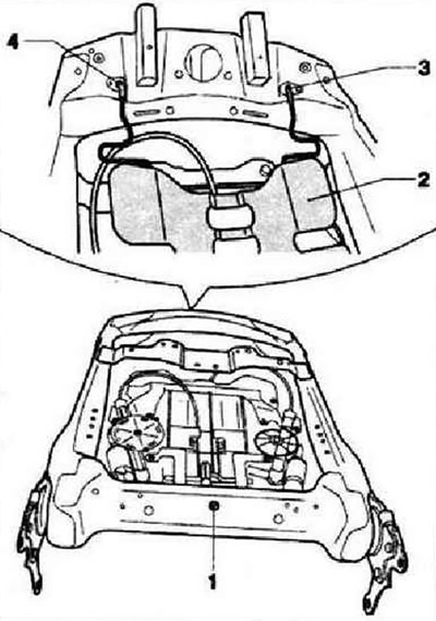
Removal and installation of the backrest adjustment drive
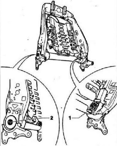
Position seat repair bracket -VAS 6136- on stand -VAS 6095-. Remove the front seat. Attach seat to bracket -VAS 6136-. Remove the front seat belt buckle. Remove lining from tunnel side. Remove trim from sill side. Disconnect the two seat back actuator harnesses at the bottom of the seat frame. Remove the wiring harnesses from the seat frame. Remove seat back. Attach backrest to bracket -VAS 6136-. If present, remove the folding table from the back. Remove the front seat cushion and upholstery. Disconnect the wiring harness from the backrest adjustment motor. Remove screw -1- (7.5±1 Nm). Loosen nut -2- (8±1 Nm).
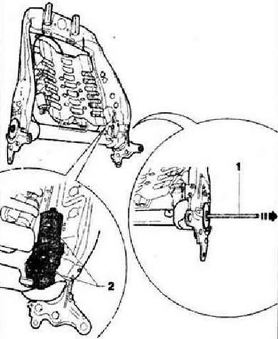
Remove drive shaft -1- from backrest -arrow-. Remove drive for backrest adjustment -2- from backrest.
Removal and installation of the drive for adjusting the angle of inclination of the pillow
Remove head restraint. Move the seat up as far as possible. Position seat repair bracket -VAS 6136- on stand -VAS 6095-. Remove the front seat. Attach seat to bracket -VAS 6136-. Remove the front seat belt buckle. Remove lining from tunnel side. Remove trim from sill side. Remove the wiring harnesses from the lower seat frame. Disconnect the harness from the seat fore and aft motor. Disconnect the harness from the cushion angle motor. Remove screws -5- and -6- at front. Detach the seat from the lower frame at the front and fold it back.
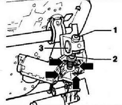
Remove screw -1-. Release screws -arrows- and remove motor.
Secure spindle -2- against rotation with pliers and unscrew spindle. Unscrew spindle -2- from nut -3-.
Installation
Screw spindle -1- of drive -2- as far as possible into nut -3-. Screw by hand (but don't drag out) screw -4- into the lead screw.
Instruction: Tighten the screw -A- to the correct torque only after the seat has been installed in the vehicle and connected to the on-board network.
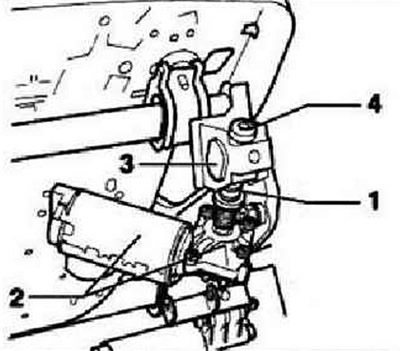
Secure drive with screw -1-, (6±2 Nm). Further installation is carried out in the reverse order. The seat is installed by you and is connected to the on-board network. Lower the airbag, using the mechanism for adjusting its inclination, and simultaneously tighten the screw -4- to a torque of 8±1 Nm.
Removal and installation of the drive height adjustment
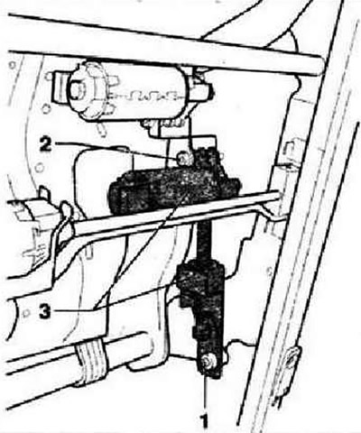
Remove head restraint. If possible, move the seat as high as possible. Position seat repair bracket -VAS 6136- on stand -VAS 6095-. Remove the front seat. Attach seat to bracket -VAS 6136-. Remove the front seat belt buckle. Remove lining from tunnel side. Remove trim from sill side. Remove trim bracket from sill side. Remove the wiring harnesses from the lower seat frame. Disconnect the wiring harness from the height adjustment motor. Remove screw -1- (18±2 Nm). Remove screw -2- (6±2 Nm). Remove drive -3- from seat frame.
Removal and installation of lumbar support (electrically adjustable in 4 directions)
Position seat repair bracket -VAS 6136- on stand -VAS 6095-. Remove the front seat. Attach seat to bracket -VAS 6136-. Remove the front seat belt buckle. Remove lining from tunnel side. Remove trim from sill side. Disconnect the two seat back actuator harnesses at the bottom of the seat frame. Remove the wiring harnesses from the seat frame. Remove seat back. Attach backrest to bracket -VAS 6136-. If present, remove the folding table from the back. Remove the front seat cushion and upholstery. Disconnect the wiring harnesses from the lumbar support adjustment motors. Drill out rivet -1- at rear of backrest Turn lumbar support -2- off backrest frame. Remove lumbar support -2- from both mounting sockets -3- and -4- located in upper front section of backrest frame.
Visitor comments