
- place the front of the car on supports;
- remove the engine protection;
- from the passenger compartment, disconnect the connection of the steering column and steering gear (see point 12.1);
- remove the connecting rod of the stabilizer bar;
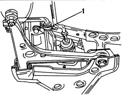
Pic. 293. Fastening 1 anti-roll bar to the subframe
- remove mounting 1 stabilizer bar from the subframe (pic. 293);
- install a jack under the subframe;
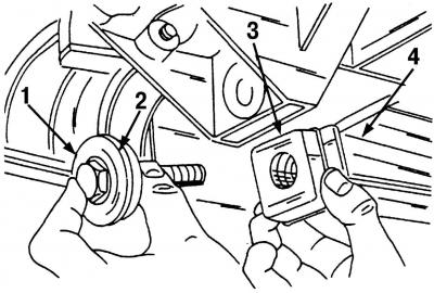
Pic. 294. Removing the pendulum support from the gearbox: 1 - bolt; 2 - washer; 3 rubber support; 4 - pendulum support
- remove the gearbox pendulum support (pic. 294). Turn away a bolt 1 and remove it together with a washer 2. Remove a rubber support 3 and wring out a pendulum support 4;
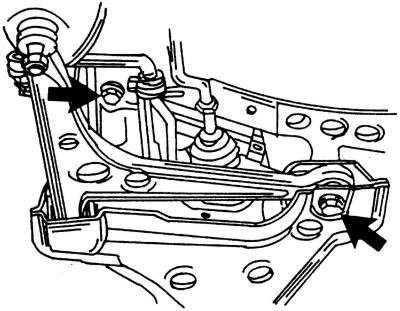
Pic. 295. On each side of the car there are two subframe mounting bolts (shown by arrows)
- Loosen the four subframe mounting bolts. Loosen two screws (pic. 295) on each side of the car;
- lower the subframe slowly and remove the anti-roll bar.
Installation is carried out in the reverse order of the removal process, while:
- do not damage the protective coating of the anti-roll bar;
- do not damage the protective covers of the hinges;
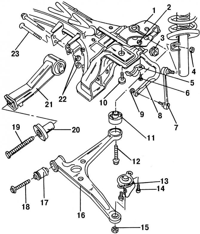
Pic. 291. Fastening the transverse arm, anti-roll bar and pendulum support on the subframe: 1 - subframe; 2 - nut, 55 Nm; 3 - rubber support; 4 - self-locking nut, 100 Nm (replace always); 5 - mounting bracket; 6 - bolt; 7 - connecting rod; 8 - anti-roll bar; 9 - self-locking nut, 100 Nm (replace always); 10 - bolt M14x1.5, 65 mm long, 150 Nm + 90°; 11 - rear bearing of the transverse arm; 12 - bolt M14x1.5, 95 mm long, 150 Nm + 90° (replace always); 13 - ball bearing; 14 - bolt, 55 Nm; 15 - self-locking nut, 55 Nm (replace always); 16 - transverse lever; 17 - transverse arm bearing; 18 - bolt, 90 Nm + 90°; 19 - bolt, 100 Nm; 20 - rubber support; 21 - pendulum support; 22 - nut, 100 Nm; 23 - bolt
- replace those shown in Fig. 291 bolts and nuts;
- tightening torques for threaded connections are listed at the end of the book.
Visitor comments