
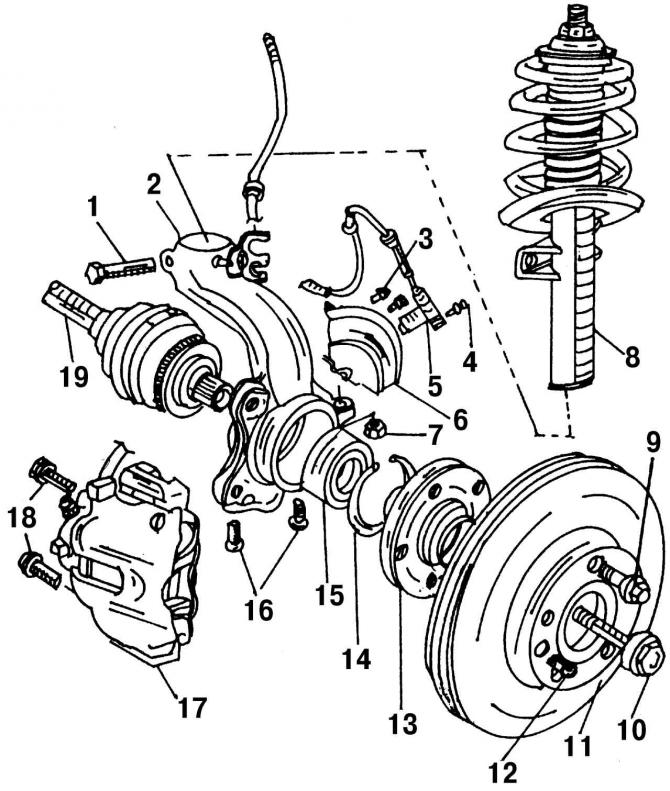
Pic. 279. Removing and installing wheel bearing, shock absorber and drive shaft: 1 - bolt, 110 Nm (replace always); 2 - rotary fist; 3 - bolt; 4 - bolt, 5 Nm; 5 - ABS speed sensor; 6 - protective cover of the hinge; 7 - nut, 30 Nm + 90°; 8 - shock absorber; 9 - wheel bolt, 140 Nm; 10 - bolt, 150 Nm + 90°; 11 - brake disc; 12 - bolt, 10 Nm; 13 - wheel hub; 14 - retaining ring of the bearing; 15 - wheel bearing housing; 16 - bolt, 55 Nm; 17 - brake caliper; 18 - bolt, 200 Nm; 19 - wheel drive shaft
Front suspension removal procedure (pic. 279):
- while the vehicle is on the ground, loosen the wheel nuts and the wheel drive shaft bolt (if the shock absorber must be dismantled). Loosen the drive shaft bolt (the total weight of the vehicle must not be carried by the wheel bearing). Remove the locks of the wheel nuts, if they were worn;
- remove the engine protection;
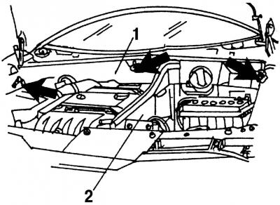
Pic. 280. Air duct (1) and wall (2) in the engine compartment (arrows show attachment points)
- remove air duct 1 in the engine compartment (pic. 280) and wall 2 of compartment AB;
- remove the expansion tank of the cooling system;
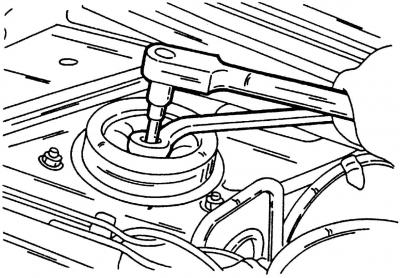
Pic. 281. Fixing the shock absorber rod
- fix shock absorber (pic. 281) in a stationary position by inserting a hexagon into the piston rod (7 mm) and take it off;
- raise the car and place it on supports;
- remove the brake hose from the shock absorber;
- remove the ABS speed sensor;
- remove the brake caliper and tie it in place with a wire without removing the brake hose;
- remove the tie rod joint nut and use a puller to squeeze the ball joint pin out of it. Protect the ball joint from dirt;
- remove the drive shaft mounting bolt from the wheel hub;
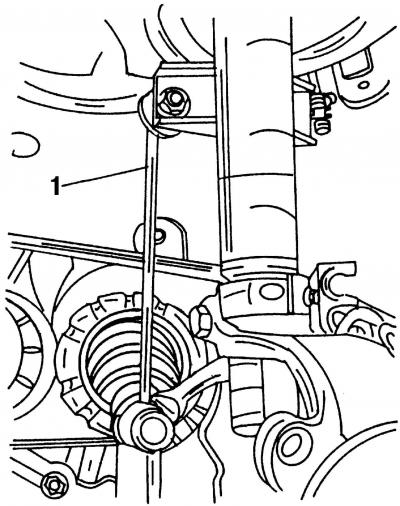
Pic. 282. Connecting rod 1 anti-roll bar fixed top and bottom
- remove the anti-roll bar link from the shock absorber mount (pic. 282). Be careful not to damage the rubber head of the tie rod when performing this operation. Replace nut.
Further stages of work are optional.
Removing the shock absorber:
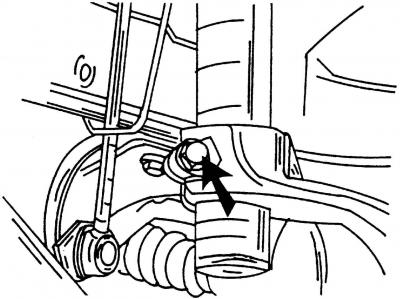
Pic. 283. Shock absorber with steering knuckle (the arrow indicates the connection bolt)
- remove the bolt at the bottom of the shock absorber (pic. 283);
- press the transverse lever down and remove the shock absorber strut;
- replace the bolt.
Removing the shock absorber with a steering knuckle:
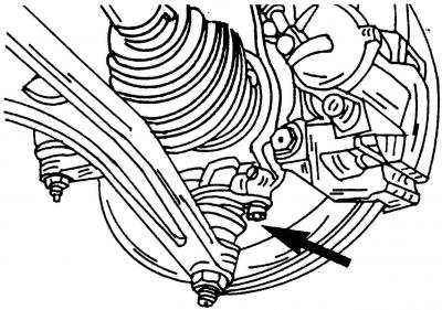
Pic. 284. Two bolts (shown by arrow) hold the bottom of the ball joint to the bottom of the steering knuckle
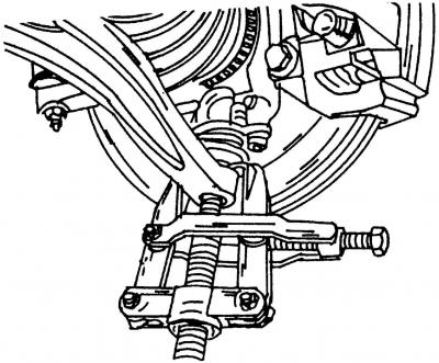
Pic. 285. Remove the pin of the ball joint from the transverse lever using a puller
- unscrew the two bolts securing the transverse lever at the bottom of the steering knuckle (pic. 284) and press it down. Remove the front suspension ball joint. To do this, remove the nut at the bottom of the transverse arm. Install puller (pic. 285) remove the ball joint from the transverse arm;
- disconnect the rod (pic. 282) and remove the shock absorber (pic. 286).
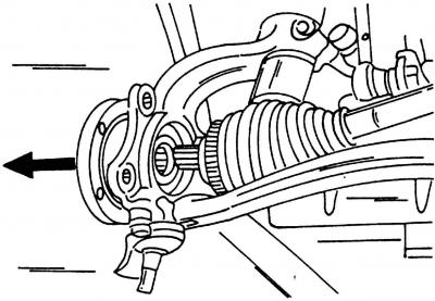
Pic. 286. Pull the steering knuckle outward so that the drive shaft is released and remove the shock absorber strut
Installation is carried out in the reverse order of the removal process.
Shock absorber installation:
- install the shock absorber strut in the upper mount and put on the limiter. Install a new self-locking nut, but do not tighten it;
- Insert the lower part of the shock absorber into the upper part of the steering knuckle so that the notch on the tube of the shock absorber is aligned with the hole on the steering knuckle. Raise the transverse arm from below. Insert a new bolt and tighten it to 110 Nm;
- fix the shock absorber piston rod in a fixed position (pic. 281) and tighten the top rack nut to 60 Nm;
- Install the anti-roll bar tie rod. tighten the nut (use a new nut) torque 100 Nm. Tighten the nut on the anti-roll bar to the same torque;
- install the tie rod joint, tighten the self-locking nut (use a new nut) with a torque of 30 Nm and tighten it another 90°;
- install the brake caliper and tighten the fastening bolts with a tightening torque of 200 Nm;
- lower the car to the ground and tighten the wheel bolts to 140 Nm;
Installing a shock absorber strut with a steering knuckle:
- install the shock absorber strut into the hole in the car body, install the rubber support and screw the shock strut mounting nut, but do not tighten it;
- install the steering knuckle (pic. 286) on the wheel drive shaft and install a new bolt with washer. Tighten the bolt to 50 Nm before lowering the vehicle onto its wheels. If the bolt is not tightened, it will damage the wheel bearing;
Attention! Do not remove the strut bearing nut without compressing the spring. Be careful not to let the spring compressor slip off the spring when it is compressed.
- Attach the connecting rod to the shock absorber. Tighten the new nut to 100 Nm;
- Install the lower ball joint to the steering knuckle. Depending on how the shock absorber was removed, either tighten the ball joint nut to 30 Nm and then turn it another 90° (always install a new nut), or tighten both bolts on the ball joint to 55 Nm;
- Install the tie rod joint on the steering knuckle. Tighten the new self-locking nut to 30 Nm and then turn it another 90°;
- install the brake caliper;
- install the wheel and lower the car on the wheels;
- tighten the drive shaft bolt to 150 Nm, and then tighten it another 90°;
Note. The bolt can only be tightened when the vehicle is on wheels.
- tighten the upper shock absorber mount;
- tighten the wheel bolts to 140 Nm.
Visitor comments