
- loosen the rear wheel bolts, put the rear of the car on supports and remove the wheels;
- disconnect the parking brake cables (see section «Brake system»);
- remove the ABS speed sensors (see section 15). Clean the ends of the sensors from contamination;
- clamp the brake hoses (to prevent leakage of brake fluid), unscrew the union nuts of the brake pipelines from the brake hoses and knock out the spring plates of the brake hose. Pull out the hose. Plug the ends of hoses and pipelines of the brake system (wrapped with adhesive tape);
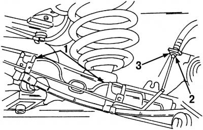
Pic. 298. Attachment points for brake hoses and pipelines on the rear suspension: 1 - clamps; 2 - nut of the pipeline of the brake drive; 3 - brake hose fastening
- release the brake lines from the clamps attached to the trailing arms of the rear suspension, and disconnect the brake hose from the line, as described above (pic. 298);
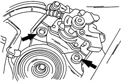
Pic. 299. Two bolts secure disc brake caliper (disc brake caliper) to the wheel hub
- remove brake calipers (pic. 299);
- remove the stabilizer bar. To do this, unscrew the bolts located at the bottom of the trailing arms, and then unscrew the bolts securing the anti-roll bar to the cross beam. Remove the anti-roll bar from the side;
- place a jack under the lower surface of the trailing arm, and raise the arm of the trailing arm so that the shock absorber compresses slightly. Remove the shock absorber mount located in its upper part;
- lower the jack slowly and remove the spring;
- place a jack under the center of the subframe;
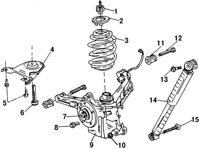
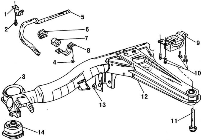
Pic. 300. Rear suspension: 1 - rubber buffer, 40 Nm; 2 - spring washer, when installing, pay attention to its correct position; 3 - spring; 4 - bearing plate of the transverse beam; 5 - bolt, 110 Nm; 6 - bolt, 170 Nm; 7 - wheel bearing block; 8 - wheel bolt, 140 Nm; 9 - trailing arm with wheel bearing housing; 10 - nut, 140 Nm (replace always); 11 - bushing of the trailing arm; 12 - bolt (replace always); 13 - bolt (replace always); 14 - shock absorber; 15 - bolt (replace always)
- unscrew bolt 8 (pic. 300) from the end of the bracket. This bolt cannot be reused;
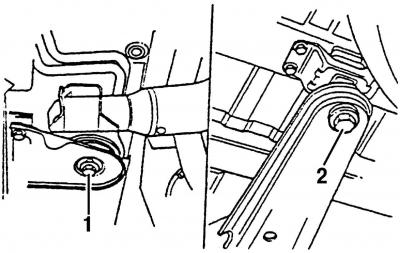
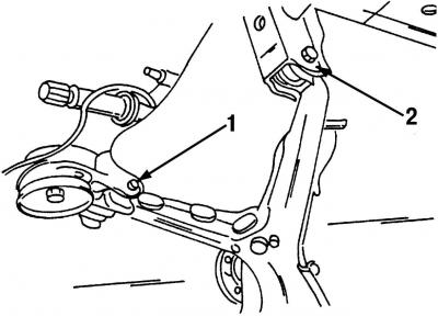
Pic. 302. Fastening of the base plate 1 and bracket 2 of the rear axle
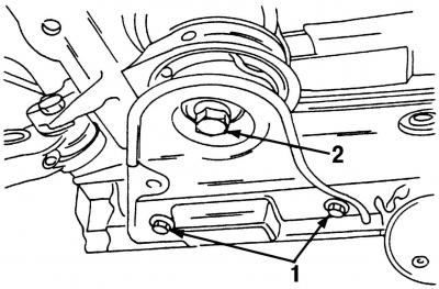
Pic. 301. Rear suspension mount: 1 - base plate; 2 - bottom of the car
- remove the rear subframe. Loosen both screws 1 (pic. 301), middle bolt 2 and remove the base plate (pic. 302). Carry out the described work on both sides of the vehicle. On fig. 300, these parts are numbered 4, 5 and 6.
- remove both shock absorbers from the trailing arms;
- remove both trailing arms. To do this, unscrew and carefully knock out the bolts. Hold the trailing arm as it may fall out.
Install the rear suspension in the following sequence:
Attention! All rubber-metal bearings should be tightened only when the weight of the car is completely on its wheels.
Pic. 303. When the wheels are on the ground, tighten connections 1 and 2 to 170 Nm
- insert the lower trailing arms into the receiving holes on the cross member and carefully drive in the bolts. Install only new bolts. Tighten both bolts to 170 Nm (pic. 303);
- Install the lower shock absorbers. Tightening torque 130 Nm. Install only new bolts;
- attach the rear suspension (pic. 302). Tighten the central bolt to 170 Nm, tighten the remaining two bolts to 110 Nm;
Pic. 304. Fastening the transverse arm of the rear suspension and anti-roll bar: 1 - bracket for mounting the anti-roll bar; 2 - bolt, 30 Nm; 3 - transverse arm of the rear suspension; 4 - bolt, 30 Nm; 5 - anti-roll bar; 6 - rubber support; 7 - rubber support; 8 - clamp of the anti-roll bar; 9 - suspension support; 10 - bolts, 65 Nm; 11 - bolt, 260 Nm; 12 - cross member; 13 - nut, 170 Nm; 14 - rubber-metal support
- set the rear suspension arm to the correct position, install a new bolt 11 (pic. 304) and tighten it with a torque of 260 Nm;
- install a jack under the trailing arm. Insert the coil spring between the trailing arm and the top support washer 2 (pic. 300). This washer has a cutout into which the end of the spring must be inserted. Jack up the trailing arm while guiding the spring (the operation is performed by two). Once the spring is properly installed, continue to raise the trailing arm so that the upper shock mount can be installed. Use only a new bolt. Tighten bolt 13 (pic. 300) and a nut with a torque of 110 Nm;
- install anti-roll bar (pic. 302). Tighten the bolts to 30 Nm;
- Connect and secure all brake hoses and lines. Tighten the nuts to a torque of 13 Nm.
Carry out the remaining operations in the reverse order of the removal process:
- install brake calipers (35 Nm);
- install wheels (140 Nm);
- remove air from the brake system;
- Tighten all rubber-metal bearing connections to the specified tightening torques. In this case, the vehicle must have a working load.
Visitor comments