
English Русский
Български
Беларускі
Український
Српски
Hrvatski
Română
Polski
Slovenský
Magyar
  |  Articles  |  Sitemap  |  Contacts  |    |
Car maintenance Ford Car maintenance Hyundai Car maintenance Chevrolet Car maintenance BMW Car maintenance Audi Car maintenance Opel Car maintenance AvtoVAZ
VWmanual.ru


Main   Passat   Golf   Polo   Touareg   Tiguan   Sharan   Transporter   Others  
LT 28 (1975-1991) LT 2D (1996-2003) Beetle (1960-1986) Caddy 3 (2003-2010)

Disassembly and assembly of the secondary shaft (VW Caddy 3)

  • Main
  • Volkswagen
  • Caddy 3
  • Transmission
  • Mechanical gearbox 0A4
  • Disassembly and assembly of the secondary shaft
            0


The secondary shaft is disassembled as follows.
  • Place a spacer puller under the 2nd gear, which rotates freely on the shaft, and remove it.
  • Remove the retaining ring.
  • Remove the 1st and 2nd gear synchronizer clutch and hub.
  • The selection of new gears or a new secondary shaft should be carried out taking into account the technical characteristics of the gearbox being repaired.
  • Tapered roller bearings are replaced in pairs.
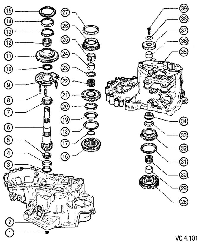
List of parts of the assembly unit «Secondary shaft» of gearbox type 0A4 with technological notes…

List of parts of the assembly unit "Secondary shaft" of gearbox type 0A4 with technological notes to figure VC4.101:
1. Hex nut: 25 Nm and tighten by turning 90°:
- 4 pcs., for fastening the bearing cup of the intermediate support.
2. Clutch housing.
3. Secondary shaft adjusting washer.
4. Outer ring of small tapered roller bearing.
5. Inner ring with cage of small tapered roller bearing.
6. Secondary shaft.
7. Inner ring with a large tapered roller bearing cage.
8. Sealing ring:
- 4 pcs., installed on the bearing cup mounting bolts of the intermediate support.
9. Bearing cup with outer ring of large tapered roller bearing and bolts:
- the outer ring is replaced only in a set with a large tapered roller bearing and bearing cup.
10. Thrust washer:
- is installed with a step towards the tapered roller bearing.
11. 1st gear freely rotating on the shaft.
12. Needle bearing of 1st gear.
13. Inner ring of 1st gear synchronizer:
- check for wear;
- check the protrusions for signs of intense wear.
14. Intermediate ring of 1st gear synchronizer:
- check for wear;
- replace if there are grooves and signs of intense wear.
15. 1st gear synchronizer locking ring:
- check for wear.
16. Clutch and hub of synchronizer 1st and 2nd gears:
- after removing the retaining ring;
- removed together with the intermediate support bearing cup.
17. Retaining ring.
18. 2nd gear synchronizer locking ring:
- check for wear;
- install so that the synchronizer clutch crackers fit into the grooves of the ring.
19. Intermediate ring of 2nd gear synchronizer:
- installed in the locking (outer) ring of the synchronizer;
- replace if there are grooves and signs of intense wear.
20. Inner ring of 2nd gear synchronizer:
- check for wear;
- check the protrusions for signs of intense wear.
21. 2nd gear freely rotating on the shaft.
22. Needle bearing of 2nd gear.
23. Thrust washer.
24. Sleeve for needle bearing of 3rd gear gear;
- is removed together with the 2nd gear gear, which rotates freely on the shaft.
25. Needle bearing of 3rd gear.
26. 3rd gear freely rotating on the shaft.
27. 3rd gear synchronizer locking ring:
- check for wear.
28. Clutch and hub of synchronizer 3rd and 4th gears:
- removed together with the 2nd and 3rd gear gears rotating freely on the shaft.
29. Needle bearing bushing:
- removed together with the clutch and hub of the synchronizer of 3rd and 4th gears.
30. Needle bearing of 4th gear.
31. 4th gear synchronizer locking ring:
- check for wear.
32. 4th gear freely rotating on the shaft.
33. Thrust washer.
34. Secondary shaft needle bearing.
35. Gearbox housing.
36. Sleeve for secondary shaft needle bearing.
37. 5th gear pinion.
38. Disc spring.
39. Screw M10: 80 Nm:
- must be replaced.


Pressing out the outer ring of a small tapered roller bearing:
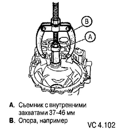
Pressing out the outer ring of a small tapered roller bearing:


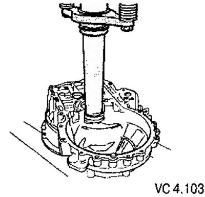
Pressing in the outer ring of a small tapered roller bearing:

Pressing in the outer ring of a small tapered roller bearing:

Removing the inner race of a small tapered roller bearing:
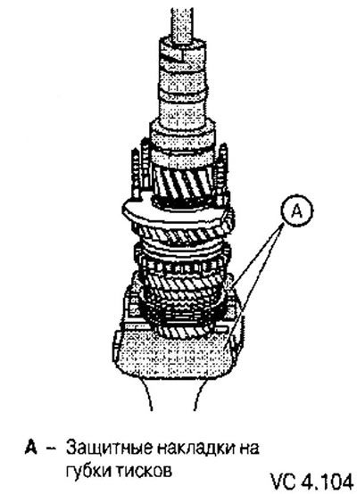
Removing the inner race of a small tapered roller bearing:


Place the clamp behind the bearing race and tighten the clamp as much as possible. After this, turn the bearing and tighten the clamp again.


The original text can be found on the portal [VWmanual.ru]

Pressing on the inner ring with the cage of a small tapered roller bearing:
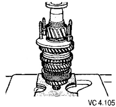
Pressing on the inner ring with the cage of a small tapered roller bearing:


Removing the hub and synchronizer clutch of 3rd and 4th gears, freely rotating on the shaft of the gears of 2nd, 3rd and 4th gears and the sleeve under the needle bearing of the secondary shaft:
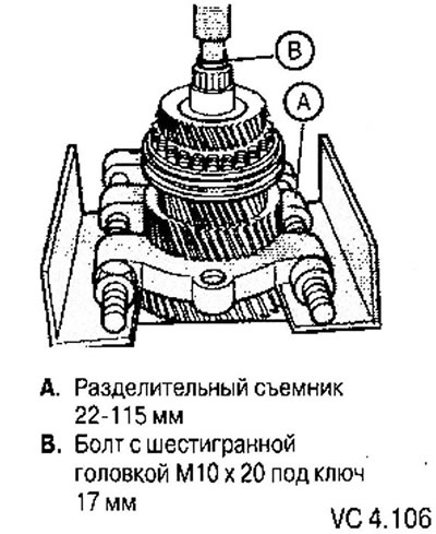
Removing the hub and synchronizer clutch of 3rd and 4th gears, freely rotating on the shaft of the…


Install the separating puller in such a way that when removing the necessary parts, the 1st and 2nd gear synchronizer sleeve is not also removed.

Removing the clutch and synchronizer hub together with the intermediate support bearing cup:
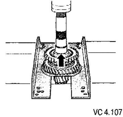
Removing the clutch and synchronizer hub together with the intermediate support bearing cup:


First, you need to remove the retaining ring (arrow).

Removing the inner race of a large tapered roller bearing:
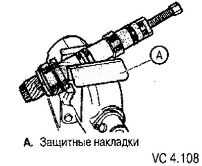
Removing the inner race of a large tapered roller bearing:


Before installing the puller, screw a hex head screw M10x20 into the hole on the end of the secondary shaft.

Pressing on the inner ring with the cage of a large tapered roller bearing:
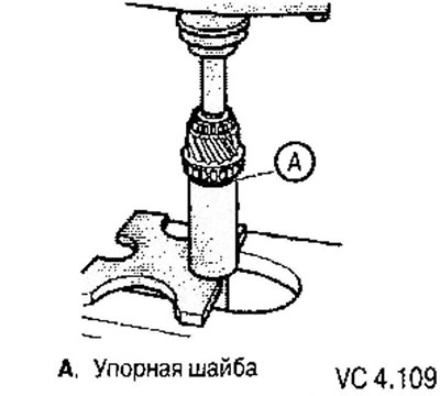
Pressing on the inner ring with the cage of a large tapered roller bearing:


Before pressing, install a thrust washer onto the shaft with the shoulder towards the inner ring.

This article is available at russian, bulgarian, belarusian, ukrainian, serbian, croatian, romanian, polish, slovak, hungarian
The text has been checked: Kolesnikov Artem

Share information:

Previous articles
Disassembling and assembling the gearshift mechanism
Adjusting the gear shift mechanism
Removal and installation the gear shift mechanism
Checking the operation of the gear shift mechanism
Gear shift mechanism
Description of the design of the 0A4 mechanical transmission
Next articles
Position of the inner, intermediate and blocking ring of the 1st gear synchronizer
Disassembly and assembly of the clutch with the synchronizer hub of 1st and 2nd gears
Pressing on the clutch and hub of the synchronizer for 1st and 2nd gears
Disassembly and assembly of the clutch with the synchronizer hub of 3rd and 4th gears


Similar articles from other manuals for VW cars:
Disassembly and assembly of the secondary shaft of the gearbox Passat B2 (1981-1988)
Secondary shaft and differential — engines 1.5/1.6/1.8 Golf 1 (1974-1984, petrol)
Removal and installation the propeller shaft Polo 4 (2001-2009)
Replacing the secondary shaft seal ring Touareg 1 (2002-2006)
Balance shaft drive chain Tiguan 1 (2007-2015)
Intermediate shaft — removal and installation Sharan 1 (1995-2000)
Speedometer shaft — removal and installation Transporter T4 (1990-2003)
Link to this page in different formats


Visitor comments


No comments yet


How much will 47 + 44 =


Caddy 3 
  • General information
  • User manual
  • Daily care
  • Maintenance
  • Petrol engines 1.4 l
  • Engine repair
  • Cooling and lubrication system
  • Power and exhaust system
  • Petrol engines 1.6 l
  • Engine repair
  • Cooling and lubrication system
  • Power and exhaust system
  • Diesel engines
  • Engine repair
  • Cooling and lubrication system
  • Power and exhaust system
  • Transmission
  • Mechanical gearbox 0AH
  • Mechanical gearbox 0A4
  • Drive shafts
  • Chassis
  • Car suspension
  • Steering
  • Brake system
  • Body and wiring diagrams
  • Interior and exterior
  • Electrical circuits
Beetle 
  • General information
  • Maintenance
  • Power unit
  • Engine repair
  • Cooling and lubrication system
  • Supply system
  • Exhaust system
  • Transmission
  • Clutch
  • Car gearbox
  • Chassis
  • Front suspension
  • Rear suspension
  • Steering
  • Brake system
  • Wheels and tires
  • Body
  • Exterior
  • Electrical equipment
  • Equipment and devices
  • Power devices
  • Electrical circuits
LT 2D 
  • General information
  • User manual
  • Maintenance
  • Power unit
  • Petrol engines 2.3 l
  • Diesel engines 2.5 l
  • Diesel engines 2.8 l
  • Injection system (diesel 2.8 l)
  • Transmission
  • Clutch
  • Manual gearbox
  • Differential
  • Chassis
  • Car suspension
  • Steering system
  • Brake system
  • Body
  • Body elements
  • Heating system
  • Electrical equipment
  • Equipment and devices
  • Electrical circuits
LT 28 
  • General information
  • Maintenance
  • Power unit
  • Petrol engines 2.0L
  • Petrol engines 2.4L
  • Diesel engines
  • Cooling and heating
  • Fuel and exhaust system
  • Ignition system
  • Transmission
  • Clutch
  • Car gearbox
  • Cardan shaft
  • Rear axle
  • Chassis
  • Brake system
  • Car suspension
  • Steering system
  • Body
  • Body elements
  • Doors, locks and windows
  • Electrical equipment
  • Power devices
  • Equipment and devices
  • Electrical circuits
VWmanual.ru © 2016-2026 | Mobile version | News and articles | Sitemap: EN BG BY UA RS HR RO PL SK HU | Write message | Site search
Passat B2 • Passat B3 • Passat B4 • Passat B5 • Passat B6 • Golf 1, diesel • Golf 1, petrol • Golf 2, petrol • Golf 2 • Golf 3 • Golf 4 • Golf 5 • Polo 3 • Polo 4 • Touareg 1 • Tiguan 1 • Sharan 1 • Transporter T3 • Transporter T4 • LT 28 • LT 2D • Beetle • Caddy 3 •
Our website uses cookies to ensure functionality and convenience.