



Section of the outer constant velocity joint
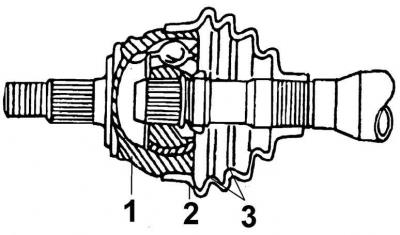
- 1 - hinge housing,
- 2 - protective cover,
- 3 - steel rings
The location of the snap ring, gasket and disc washer securing the outer joint to the drive shaft
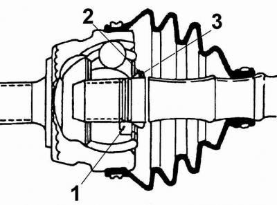
- 1 - retaining ring,
- 2 - gasket,
- 3 - disc washer
Using special tool 1683 to fasten the upgraded clamp
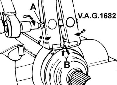
- A - screw for tightening the tool jaws,
- B - installation of the tool jaws on the clamp
The diameter of the outer constant velocity joint is different and is 88.0 or 98.0 mm.
Execution order
1. Remove the clamps securing the protective cover and slide the cover off the hinge and onto the drive shaft.
2. Thoroughly clean the inside of the joint and remove the snap ring from the inside of the joint.
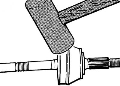
3. Secure the drive shaft in a vice with soft jaws and use an aluminum or brass hammer to knock the joint off the drive shaft.
4. Remove the snap ring, gasket and Belleville washer from the end of the drive shaft.
5. Fill the inner joint with 90 grams of grease.
6. Install the disc washer onto the drive shaft, with the convex side facing the joint, see Fig. Location of the retaining ring, gasket and disc washer securing the outer joint to the drive shaft.
7. Install a new snap ring on the drive shaft, secure the shaft in a vice with soft jaws and use an aluminum or copper hammer to tap the joint onto the drive shaft until the snap ring fits neatly into the groove on the inside of the joint.
8. Install the protective cover on the hinge and secure it with clamps. Before securing the protective cover with clamps, use a screwdriver to lift the inner edge of the cover to equalize the air pressure under the cover. To secure the clamps, use tool 1683 (see Fig. Using special tool 1683 to fasten the upgraded clamp). Place the jaws of the tool on the corners of the clamp clamp and tighten the jaws with a screw in this position.
Visitor comments