



Contents: Removal ↓ Installation ↓
Removal
1. Check the play of the tie rod end. To do this, jack up the front of the car so that the front wheels hang freely. Move the wheels and tie rods from side to side. There should be no play.
2. Set the wheels to move straight.
3. Mark the direction of rotation of the wheel with an arrow on the sidewall of the tire and loosen the wheel bolts.
4. Jack up the front of the car, place it on support stands and, after unscrewing the mounting bolts, remove the wheel.
5. Check the fastening of the tie rod end, as well as the condition of the ball joint protective caps and their fit. If necessary, replace the end with a new one.
6. Loosen the nut 1 of the ball joint pin of the tie rod end by several turns. At the same time, hold the tip pin from turning with a T40 multi-sided socket wrench (see illustration).
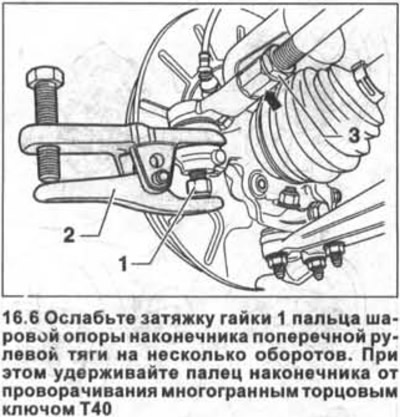
7. Press out the ball joint pin of the end from the steering knuckle arm using a puller, for example, HAZET 779, resting the puller on the nut on the pin (see illustration 16.6).
8. Unscrew the nut from the tip pin completely and remove the pin from the lever on the steering knuckle.
9. Mark the position of the tie rod and the end relative to each other so that when installing, tighten the lock nut 3 as it was before removal (see illustration 16.6).
10. Loosen the lock nut 3 while holding the tie rod end with a wrench (see arrow in illustration 16.6).
11. Unscrew the tip from the tie rod, counting and recording the number of turns. This data will be needed when installing the tip.
Installation
The ends of the transverse steering rods are marked. The letter A indicates the ends of the right steering rod, and the letter B indicates the ends of the left steering rod.
12. Degrease the tie rod end rod.
13. Screw the tip to the tie rod using the same number of turns as when removing it.
14. Tighten lock nut 3 by hand (see illustration 16.6).
15. Align the tie rod so that the end pin is in the correct mounting position and insert the pin into the hole on the steering knuckle arm until it stops.
16. Screw on the new nut 1 (see illustration 16.6) onto the ball joint pin of the tip and tighten it with a force of 20 Nm, and then turn it further by 1/4 turn (90°).
Caution: Use a T40 socket wrench to prevent the tip pin from turning.
17. Tighten the lock nut on the tie rod with a force of 55 Nm. When tightening the lock nut, hold the tie rod from turning by the hexagonal collar.
18. Install the removed wheel in accordance with the marks made during removal.
19. Screw in the wheel bolts and lower the car onto its wheels.
20. Tighten the wheel bolts in a criss-cross pattern to a torque of 120 Nm.
21. Contact a workshop to check the wheel alignment.
Visitor comments