



Contents: Removal ↓ Installation ↓
Steering gear
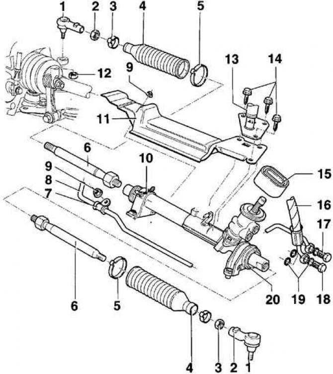
- 1 - tie rod end;
- 2 - nut, 50 Nm;
- 3 - clamp. When installing, it is necessary to use a new clamp;
- 4 - protective cover;
- 5 - clamp. When installing, it is necessary to use a new clamp;
- 6 - steering rod, 75 Nm;
- 7 - clamp with rubber;
- 8 - supply pipeline;
- 9 - nut, 22 Nm;
- 10 - clamp with rubber support. When installing the clamp, the arrow on it should point to the front of the car;
- 11 - heat-protective sheet screen;
- 12 - self-locking nut, 45 Nm. A new nut must be used during installation;
- 13 - bracket;
- 14 - bolt, 24 Nm;
- 15 - seal;
- 16 - hydraulic pipe;
- 17 - hollow bolt M 16x1.5, 45 Nm;
- 18 - hollow bolt M 14x1.5, 40 Nm;
- 19 - O-rings. New O-rings must be used during installation;
- 20 - steering gear
Power steering pump with bracket (installed at the bottom)
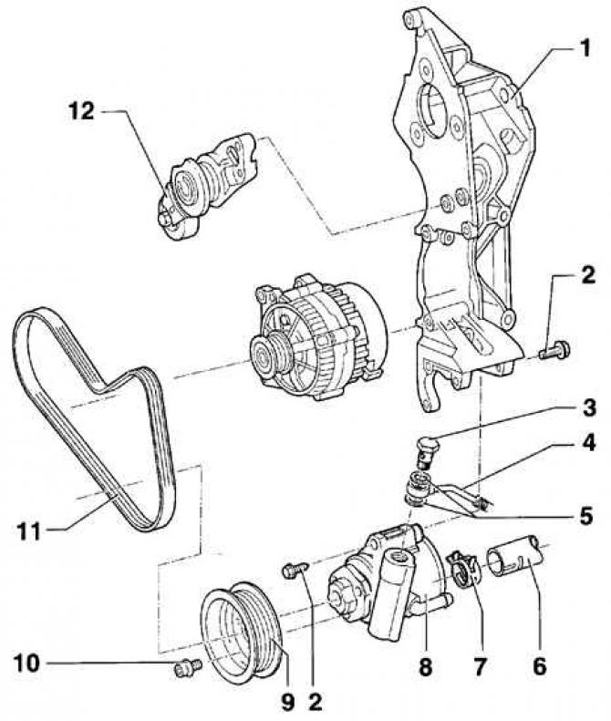
- 1 - bracket;
- 2 - bolt, 25 Nm;
- 3 - hollow bolt, 30 Nm;
- 4 - discharge pipeline;
- 5 - O-ring. A new O-ring must be used when installing;
- 6 - suction pipe;
- 7 - clamp;
- 8 - Power steering pump. Before installation, fill the pump with power steering fluid. Pour fluid into the suction pipe of the pump and turn the pump shaft by hand until fluid appears in the discharge pipe;
- 9 - belt pulley;
- 10 - Allen bolt, 25 Nm;
- 11 - poly V-belt;
- 12 - Poly V-belt tensioning mechanism
Power steering pump with bracket (mounted at the top)
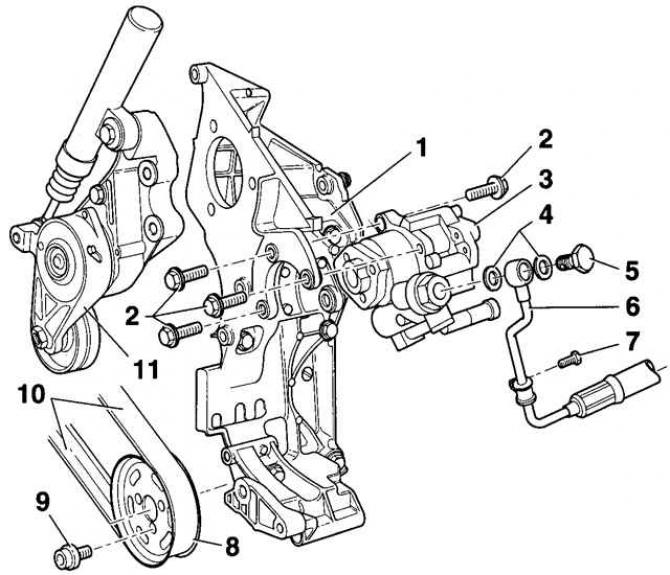
- 1 - bracket;
- 2 - bolt, 25 Nm;
- 3 - Power steering pump;
- 4 - sealing ring;
- 5 - hollow bolt, 30 Nm;
- 6 - discharge pipeline;
- 7 - bolt, 22 Nm;
- 8 - belt pulley;
- 9 - Allen bolt, 25 Nm;
- 10 - poly V-belt;
- 11 - Poly V-belt tensioning mechanism
The steering rod ends must not have any play. If the protective covers are damaged, they must be replaced immediately. The steering rod ends can be replaced without removing the steering gear.
Removal
1. Loosen the front wheel mounting bolts, then raise the front of the vehicle and support it on stands.
2. Remove the front wheel.
3. Unscrew the tie rod ball joint mounting nut, while holding the ball joint pin from turning with a hex wrench.
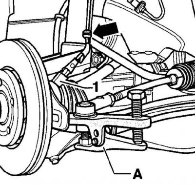
4. Unscrew the nut to the end of the thread, but do not unscrew it completely, while it will serve as a stop for the puller (1 - ABS sensor electrical connector, A - ball joint puller).
5. Disconnect the ABS sensor electrical connector.
6. Using a ball joint puller, remove the tie rod end ball joint from the steering knuckle.
7. Unscrew the lock nut 2 (see picture Steering gear), fixing the steering rod in relation to the steering rod end.
8. Unscrew the tie rod end from the tie rod, while counting the number of turns made by the tie rod end.
Installation
1. Screw the tie rod end onto the tie rod using the same number of turns as when unscrewing it.
(The text is copied from this portal: «VWManual»)
2. Tighten lock nut 2 (see picture Steering gear) by hand.
3. Insert the ball joint of the tie rod end into the steering knuckle and secure it with a new self-locking nut, tightening it to a torque of 45 Nm. While tightening the nut, hold the ball joint pin from turning with an Allen key.
4. Tighten the lock nut to 50 Nm.
5. Connect the ABS sensor electrical connector.
6. Install the wheel and secure it with bolts.
7. Lower the vehicle to the ground and tighten the mounting bolts to 120 Nm.
8. Check and, if necessary, adjust the wheel alignment angles.
Visitor comments