



Each of the electrical circuits that feed the consumers has a fuse of the appropriate power. To feed consumers that consume high current, a relay is used. In this case, two circuits are distinguished: one is low current, controlling the switching on and off of the relay, and the second is high-voltage current, connected to the relay contacts, which are adapted to connect high-current. Usually, on one side, the current flows to the relay directly from the battery and through the high-voltage current contacts to a specific consumer.
An electrical diagram presents individual electrical circuits in an orderly fashion, making it possible to navigate the laying of electrical wires.
The horizontal lines at the top of each diagram represent the connections in the relay plate. The black dots at the intersections of the wires represent the non-disconnectable connections of those wires. The symbols for disconnectable connections have numbers written next to them, for example, 2/45, where:
2 - indicates the contact number on the relay plate;
45 - indicates the contact number (for example, relay), inserted into the plate.
All switches are shown in the diagrams in the "off" position. The vertical lines represent the wire bundles, and the lower horizontal lines symbolize the vehicle's ground, see Figure 4.18 and 4.19.
To facilitate the search, the composition of graphic symbols used in the diagrams (list) is indicated. To find a specific consumer, it is necessary to first select from the composition of the diagrams the one on which it can be located. If it is necessary to find a generator, the diagram with the name "Generator" is located first. On this diagram, the generator is found using graphic symbols, data in the figure or alpha-number designations, bottom in point 41 (figure 4.19). Near the graphic symbol, at the point where the wires are connected, there is a number that determines the clamp number on the consumer. The wire must be connected to the clamp of the consumer of this number. The same must be done with the numbers of the outputs from the relay box and the numbers near the ground. The numbers in the circles near the busbar ground are used to find the "ground point" on the body. The approximate position of the "ground point" can be determined based on the information given in paragraph 42.
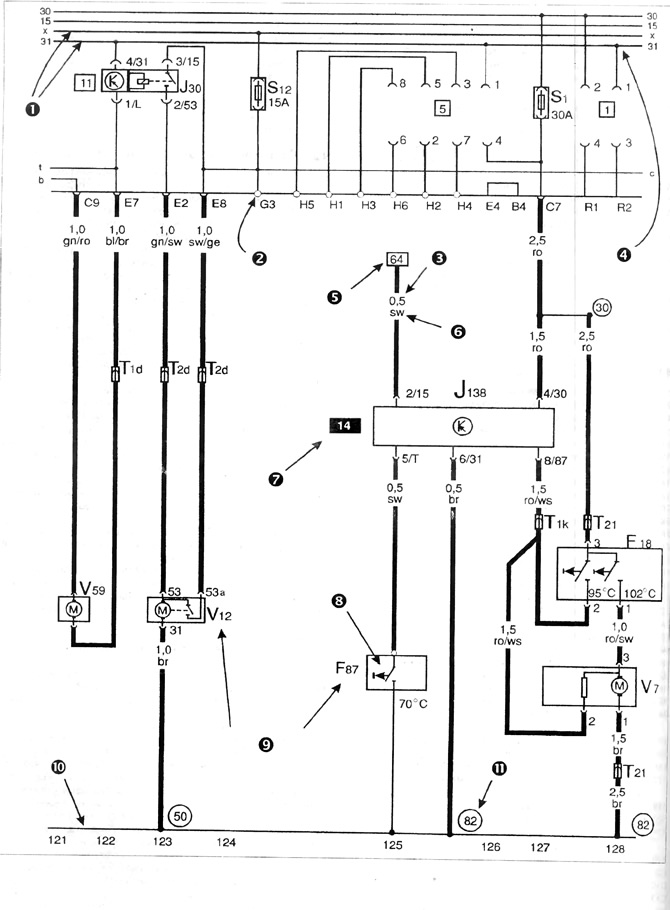
Figure 4.18. Example of symbols used in electrical circuits
1 - tracks on the relay plate; 2 - connection is detachable; 3 - wire cross-section; 4 - non-separable connection; 5 - relation to the chain in which the track goes further; 6 - wire color designation; 7 - relay location number on the plate; 8 - graphic designations of elements (figure 4.19); 9 - alpha-nomeral designations; 10 - weight of the car (electric); 11 - points of mass.
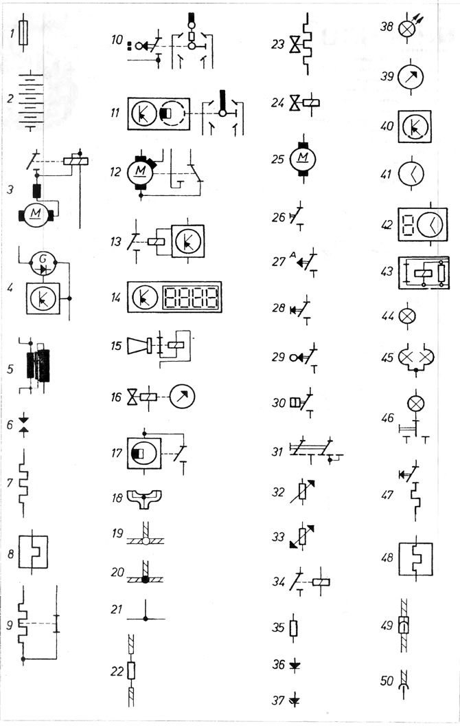
Figure 4.19. Graphic symbols of the electrical circuit
1 - fuse; 2 - battery; 3 - starter; 4 - generator; 5 - ignition coil; 6 - spark plug electrodes; 7 - glow plug, heating resistor; 8 - automatic carburetor starting system; 9 - temporary thermal switch; 10 - ignition distributor, mechanical; 11 - ignition distributor, electronic; 12 - Two-stage wiper switch; 13 - electronically controlled relay; 14 - Multifunctional Projector; 15 - sound signal; 16 - flow indicator; 17 - speedometer sensor (speedometer); 18 - wire distributor; 19 - detachable connection; 20 - non-separable connection; 21 - connection inside the equipment; 22 - support wire; 23 - engine preheating valve, additional air valve; 24 - electromagnetic valve; 25 - Electric motor; 26 - Manually operated switch; 27 - bimetallic switch; 28 - Manually operated button; 29 - mechanically controlled button; 30 - pressure controlled switch; 31 - multi-contact switch, manually switched on; 32 - fuel level sensor; 33 - coolant temperature sensor; 34 - relay; 35 - rheostat; 36 - diode; 37 - Zeneid diode; 38 - LED light; 39 - deviation indicator; 40 - electronic command controller; 41 - clock with hands; 42 - digital clock; 43 - Sound signaling device; 44 - lamp; 45 - double filament lamp; 46 - Interior lighting lamp; 47 - cigarette lighter; 48 - heated rear window; 49 - plug connection; 50 - multi-pin plug connection.
Visitor comments