
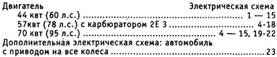
Use of electrical diagrams
Up to 1,000 meters of electrical wiring has been laid in a passenger car to provide electricity to all consumers (headlights, radio, etc.).
Electrical diagrams are necessary when troubleshooting electrical equipment and when installing additional equipment; according to the schemes, the passage of signals and the laying of cables are traced. The corresponding current circuit must necessarily be closed, otherwise no electric current will flow through this circuit. For example, it is not enough to apply only plus voltage to the headlights, by connecting them simultaneously to ground.
Therefore, the ground wire from the battery is connected to the body. However, this earth connection is often not enough, and the corresponding consumer is connected to earth directly by a earth wire, the insulation of which is usually brown. Separate current circuits include relays, switches, fuses, measuring elements, electric motors and other electrical elements. For their correct connection, these elements are marked on their contacts.
For ordering on the electrical circuits of the interweaving of wires, individual current circuits are arranged vertically on the diagrams and numbered.
The vertical lines at the top end in a field with a gray background, which displays the relay board with fuse holders, that is, the positive connections of the current circuits. However, the relay board also has an internal ground wire (terminal 131).
The thin lines in this field show how and which current circuits are connected to each other in the relay board.
At the bottom, the vertical lines connect to a horizontal line representing ground connections. The ground connection is usually made by connecting the unit body to the body, however, in some cases, ground can be supplied through a separate wire from the ground point on the body.
If a current circuit is interrupted by a square inside which a number is indicated, this number indicates the current circuit in which the current circuit continues.
It is best to use electrical circuits as follows:
First, according to the legend, the corresponding circuit element is found, for example, a fan switch. In the right column, next to the name of the element, the corresponding current circuit with its number is indicated, which is also indicated on the electrical diagram below on a horizontal line.
To read an electrical circuit, you need to know the designations of some elements, in addition, you should know the most important symbols of electrical circuits.
For more accurate identification, letter designations are supplemented with serial numbers.
Relays and control units are usually displayed on a gray background. The lines on this background represent inner connections. They show how relays and other electrical and/or electronic components are connected both to each other and on the relay board.
The number in the black square indicates the location number of the relay on the relay board with fuse holders. Directly at the relay are the designations of the contacts.
Example: If the terminal on the wiring diagram is labeled 17\87, then 17 is the terminal label on the relay board and 87 is the terminal label on the relay or electronics.
Terminal designations are standardized no DIN. The designations of the most important terminals are as follows:
- Terminal 30. Battery voltage is always present at this terminal. The wires are most often red or red with colored stripes.
- Terminal 31 is connected to ground. The wires connecting with ma-soy are mostly brown.
- Terminal 15 is powered by the ignition switch. Voltage is present at the terminal only after the ignition is turned on. Wires are most often green or with colored stripes.
The X terminal is also energized only when the ignition is on, but the voltage is removed after the starter is started. This ensures that full voltage is supplied during engine start. All powerful energy consumers are located in this current circuit. High beam headlights are also powered through this terminal. So when the high beam is on, it automatically switches to the parking light when the ignition is turned off. '
Electrical circuits
Release model 1991
Due to the large volume, all models of each year of manufacture cannot be taken into account. However, owners of cars from earlier years of production can refer to the wiring diagrams shown here, since the current changes concerned only parts.
Distribution of electrical circuits
The location of the relay pads on the relay board
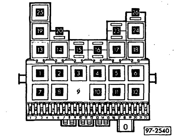
3 - Control unit signaling a decrease in the level of coolant (43)
5 - Relay 2nd stage radiator fan (53)
7 - Fog lamp relay (53)
8 - Unloading relay contact X (18)
10 - Relay for automatic intermittent operation of the wiper and washer (19)
11 — the Relay of a screen wiper and a washer of back glass (72)
12 - Alarm relay (21) or beacon relay when using a trailer (22)
13 - Headlight washer relay (33)
14 - Fuse rear fog lights
16 - Fuse, terminal 58b
In parentheses is the production index-relay indicated on its body.
Pads - connectors
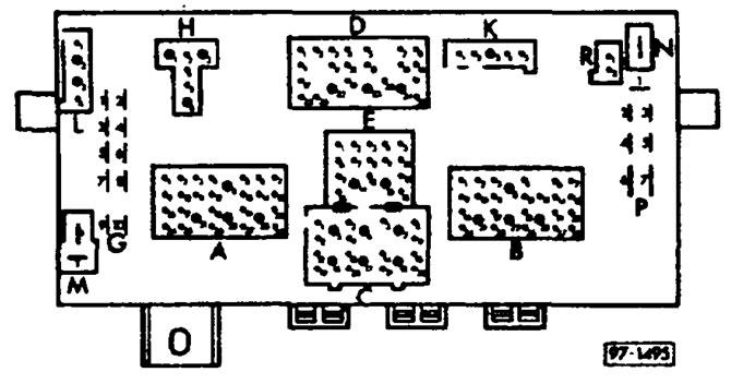
A. Multi-pin connector (blue) for connecting the dashboard wiring harness
B. Multi-pin connector (red) for connecting the dashboard wiring harness
C. Multi-pin connector (yellow) for connecting the front wiring harness
D. Multi-pin connector (white) to connect the wiper wiring harness and the main wiring harness
E. Multi-pin connector (black) for connecting the main wiring harness
F. Single connector
H. Multi-pin connector (brown), radiator fan relay connection, 2nd stage
K. Multi-pin connector (colorless), connection of the coolant level alarm control unit
L. Multi-pin connector (grey), double tone horn connection
M. free
N. Single connector
P. Single connector - terminal 30
R. free
Fuse colors:
- 30 A - green
- 25 A - white
- 20 A - yellow
- 15 A - blue
- 10 A - red
Visitor comments