
To replace the rubber joint, lift and support the rear of the vehicle (see chapter "Basic rules for work"). Remove the nut and pivot bolt securing the bridge to the bracket. Remove the two nuts securing the bracket to the body and remove the bracket.
If one of the studs breaks when loosening the bracket fastening nuts, drill out the rest of the stud with an 8 mm drill and cut an M10 thread in the hole. To fasten the bracket, use M 10x40 bolts (high strength, class 10.9).
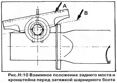
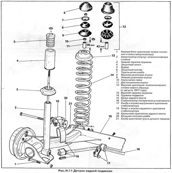
When installing a new bracket, remember that the Belleville washer is installed on the outside of the pivot, the large flat washer is placed between the bracket and the axle arm, and the small flat washer is placed under the nut on the inside of the arm when the pivot bolt is installed (pic. H:11). Rotate the lever relative to the bracket before tightening the pivot bolt as shown in fig. H:10 - edge of the bracket "A" must be parallel to the line "IN". Tighten the pivot bolt to 7.0 kNm.
Rear axle
If necessary, the rear axle can be removed complete with telescopic struts. To do this, disconnect the hand brake cables from the brake shoe levers, and the brake hoses from the brackets on the bottom of the body (see chapter "Brake system"). Then disconnect the top mounts of the telescopic struts (see section "shock absorbers") and rear axle joints as described above.
The installation of the bridge is carried out in the reverse order. Bleed the brakes and adjust the handbrake cables as described in chapter "Brake system".
Roll Stabilizer
The rear anti-roll bar is installed on performance models with 1.6 and 1.8 liter injection engines. The stabilizer is attached at both ends to the rear axle levers with metal clamps through rubber bushings, and to the axle beam with two brackets and bushings.
To replace the stabilizer, raise the rear of the vehicle and place it on jack stands.
Bend down the tongues of the clamps, remove the retaining plates (18, fig. H:11) and remove the clamps, then unscrew the nuts and bolts of the brackets of the internal fastening (17, fig. H:11) and remove the stabilizer.
Installation of the stabilizer is carried out in the reverse order.
Visitor comments