



Contents: Test drive before balancing ↓ Balancing on a stationary balancing…↓ Procedure for wheel/tire balancing ↓ Minimization ↓ Balancing test stand VAS 6230 ↓
Before you begin balancing, the following conditions must be met.
The air pressure in the tire must be normal.
The tread pattern must not have one-sided wear, and its depth must be at least 4 mm.
The tire should not have any damage, such as cuts, punctures, foreign objects, etc.
The wheel suspension, steering, steering rods, including shock absorbers, must be in perfect condition.
Test drive before balancing
If a car is brought to an authorized station with a complaint about "unsmooth running", then before balancing it is necessary to perform a test drive.
In this case, the technician must familiarize himself with the nature of the malfunction.
While driving, you should determine at what speed the imbalance appears.
Immediately after the test drive, raise the car on a lift.
Mark the installation location on each tire.
Remove the wheels and balance the wheels.
Balancing on a stationary balancing stand
Clamp the wheel on the balancing stand.
NOTE: It is important to remember that when balancing wheels, as with any other repair, the most important rule is cleanliness. Only by monitoring cleanliness can you achieve a perfect result. Dirt and rust in the area of the wheel mating and centering hole distort the result.
Before installing the wheel on the balancing machine, clean the mating surface, centering hole and disc.
Place the wheel and tire on the balancing stand.
NOTE: To tighten the wheel, use, for example, the collet self-expanding adapter for balancing stands K4S 5271 (Fig. 4.13).
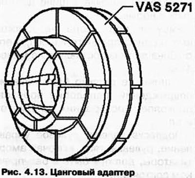
When used, it guarantees 100% wheel centering and gentle disk clamping.
Conical centering adapters do not provide 100% wheel centering on the stand.
A 0.1 mm deviation from the center results in an imbalance of 10 grams on the wheel and tire.
Procedure for wheel/tire balancing
Spin the wheel and tire on the balancing stand.
Check the alignment of the marking strips on the sidewalls of the tyre in the area of the bead flange.
Check the tread pattern while the wheel is rotating.
NOTE: If there is one-sided wear, wear spots due to braking with locked wheels, or severe uneven wear, balancing will not achieve a smooth ride. In this case, the tire must be replaced.
Check the accuracy of rotation of the wheel with the tire. If the wheel with the tire rotates unevenly, although there is no flattening of the tire, the cause may be radial and lateral runout.
Check the wheel and tire for radial and lateral runout.
If the radial and lateral runout are within tolerance, balance the wheel and tire.
NOTE: Do not use more than 60 grams of weight per wheel. If more weights are needed, good balance can be achieved by minimizing them if necessary.
Minimization
The balancer display should show 0 grams.
As an alternative to minimization, you can use the VAS 6230 balancing stand.
Screw the wheel to the hub.
First tighten the lowest wheel bolt to approximately 30 Nm.
Then tighten the remaining bolts to 30 Nm in a crisscross pattern. This will center the wheel on the hub.
Lower the car onto its wheels.
Now tighten the wheel bolts in a crisscross pattern using a torque wrench to the specified torque.
After balancing the wheels, take a test drive.
If you still feel a vibration during a test drive, it may be due to a balancing error due to wheel centering.
Wheel and hub alignment errors can overlap in unfavorable cases. For this reason, runout is also possible. This can be eliminated using a final balancing stand
Balancing test stand VAS 6230
With the help of the balancing test stand VAS 6230, in addition to the well-known static balancing, additional functions can be performed (Fig. 4.14).
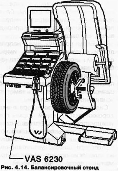
The peculiarity of this system is the checking of the radial force of the wheel with the tire during rotation.
During this test, a roller presses on the wheel with a force of approximately 635 kg. This simulates the force acting on the bearing surface of the wheel from the road surface during movement.
Due to radial and lateral runout in the wheel and tire and different stiffnesses in the tire, the forces acting on the tire-road contact area vary.
The VAS 6230 system detects and stores the position of the maximum measured radial force in the tyre. This is used to measure the position of the smallest distance between the rim flange and the centre of the disc.
Visitor comments