
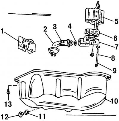
Pic. 452. View of the oil sump and disassembled oil pump: 1 - guide plate; 2 - oil receiving pipe; 3 - a bolt of an oil receiving pipe, 10 Nm; 4 - sealing ring, 10 Nm; 5 - oil pump housing; 6 - gears of the oil pump; 7 - cover of oil pumps with a pressure reducing valve; 8 - short cover bolt, 10 Nm; 9 - long cover bolt, 25 Nm; 10 - oil sump; 11 - sealing ring (always replace with a new one); 12 - drain plug, 30 Nm; 13 - oil sump mounting bolt, 25 Nm
The way of fastening of the oil pump is shown in fig. 452. When removing, proceed as follows:
- remove the oil pan (subsection 18.1);
- unscrew the bolts of the oil pump housing;
- pull the pump down so that the shaft disengages, and then pull it out completely;
- remove the vacuum pump from the top of the engine and remove it upwards, as it must be removed when installing the pump;
Installation of the pump is carried out in the reverse order of the removal process, however, the following recommendations should be observed:
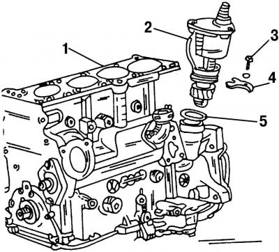
Pic. 453. Location of the brake booster vacuum pump on the cylinder block: 1 - cylinder block; 2 - vacuum pump; 3 - bolt, 25 Nm; 4 - clamping plate; 5 - sealing ring
- install a vacuum pump. It is mounted together with a sealing ring, which is replaced with a new one. Insert the pressure plate into the groove of the shaft and tighten the bolt to 20 Nm. On fig. 453 shows a way to mount a vacuum pump;
- insert the oil pump drive shaft from below through the engine into the inside of the vacuum pump drive mechanism and press on the oil pump without gasket to the crankcase;
- tighten the bolts to a torque of 25 Nm;
- reinstall the oil sump and fill the engine with oil.
Visitor comments