



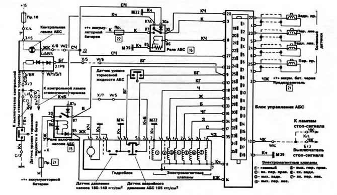
Fig. 7-8. Schematic diagram of the Teves ABS
Pr. - fuse;
M is the ground connection point, the numbers next to the letters indicate the fuse number or ground connection point.
W/1 etc. - the letter indicates the connector in the relay block, the number is the pin number on the connector. The numbers in the squares indicate the relay block or fuse holder number.
Wire color designation:
B - white;
G - blue;
Y - yellow;
3 - green;
K - red;
Kch - brown;
C - gray;
Ch - black.
The first letter indicates the color of the wire itself, the second indicates the color of the stripe on the wire.
Before checking, make sure that the fuses are intact, that the electronic control unit is securely connected to ground, and that the battery is charged normally.
(The information is posted on this website: «VWManual»)
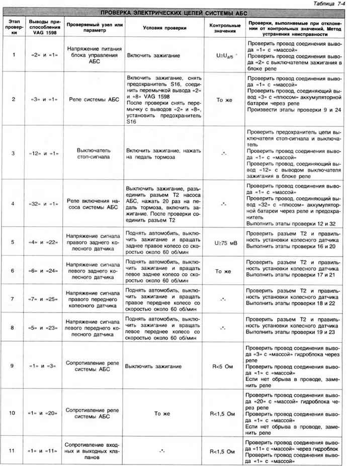
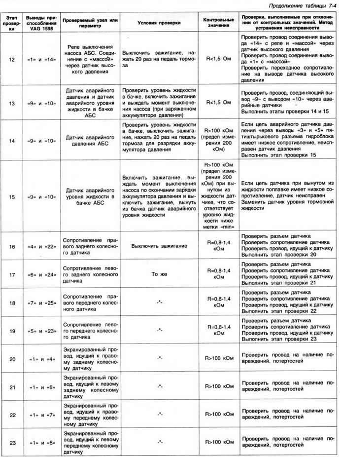
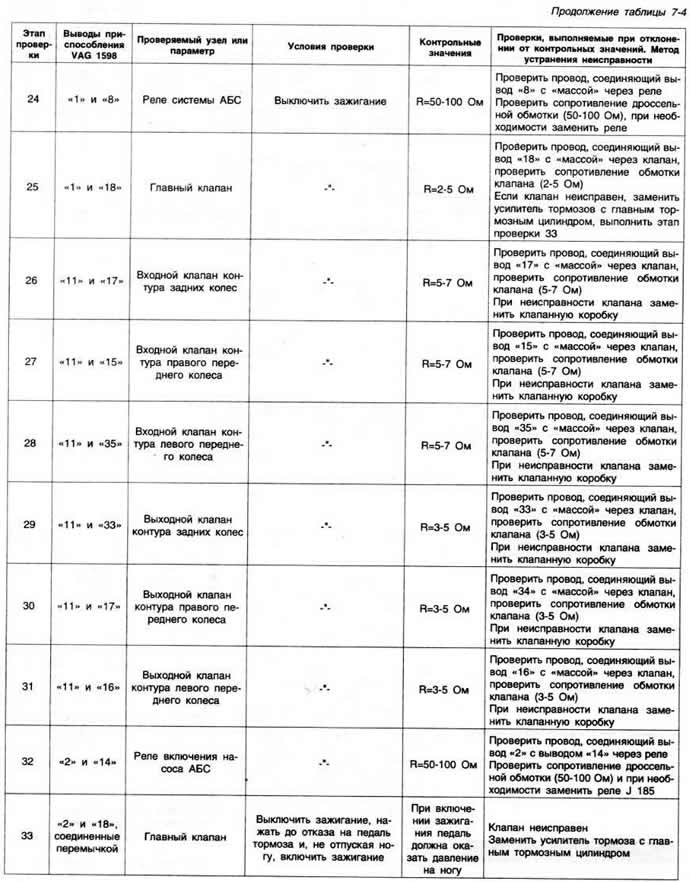
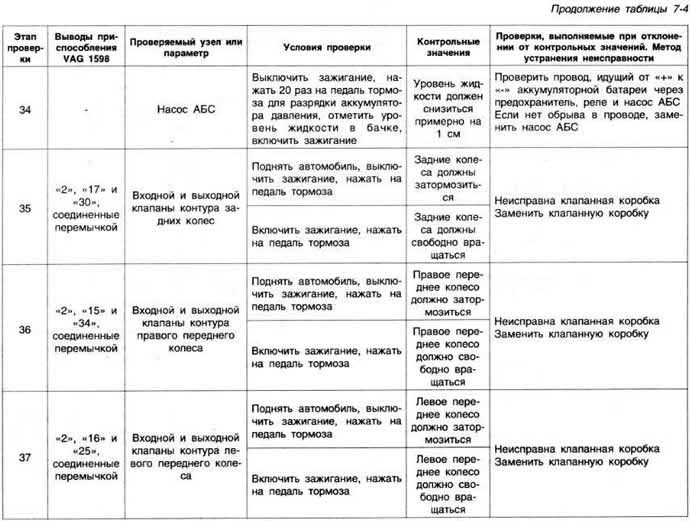
In order not to damage the terminals of the electronic unit connector during testing, it is recommended to connect the control devices via a terminal block with the same terminal numbers as the connector terminals. When testing, follow the instructions in Table 7-4.
Visitor comments