
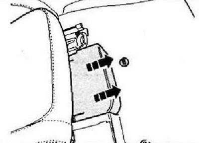
Switch off the ignition and all electrical consumers, remove the ignition key. Detach cover under seat in -direction of arrow-.
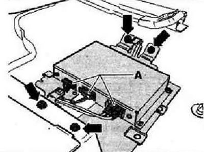
Disconnect connectors -A- and remove four screws -arrows-. Remove digital satellite radio with bracket.
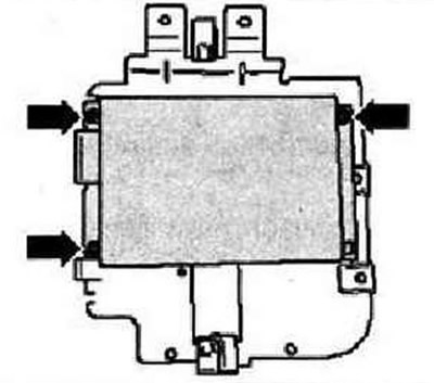
Remove screws -arrows- while holding nuts on opposite side to prevent turning.
Digital satellite radio connectors
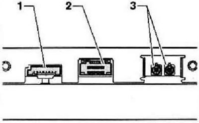
- 1 - Connector for the transfer of digital information from the device / to the device
- 2 - Power connector
- 3 - Antenna connectors
Pin arrangement in connector 1
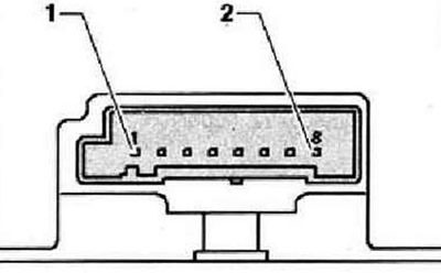
- 1 - CAN low bus
- 2 - CAN high bus
- 3 - CDX, left channel, input
- 4 - CDX, right channel, input
- 5 - Audio, minus
- 6 - Audio, output, left channel, plus
- 7 - Audio, output, right channel, plus
- 8 - CDX, minus
Pin assignment in connector 2
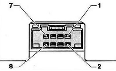
- 1 - Power supply, minus
- 2 - Power supply, plus
- 3 - Not used
- 4 - Not used
- 5 - Not used
- 6 - Not used
- 7 - Not used
- 8 - Not used
Location of connectors for connecting antennas
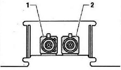
- 1 - Antenna input for receiving signals from stationary digital radio stations, brown connector
- 2 - Antenna input for receiving signals from satellites, green connector
Vehicles from 11.06 have only one connector in this location.
Visitor comments