



Instructions: When troubleshooting the radio/radio navigation system, it is necessary to know how it works and is controlled. When repairing or troubleshooting, use the VAS 5051 tester or VAS 5052 tester or their later modifications in the Guided Fault Finding mode. After connecting the battery, it is necessary to check the vehicle equipment (radio, clock, electrical equipment of comfort systems).
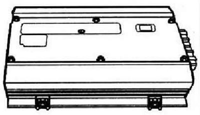
The amplifier is an additional component for the radio/radio navigation system and serves to improve its sound. The corresponding amplifier model is installed on request in addition to the radio/radio navigation system. The amplifier has 8 channels. The amplifier signal inputs are controlled via the radio or radio navigation system outputs intended for connecting speakers. The amplifier is installed under the front left seat.
Removal
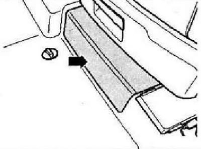
Turn off the ignition and all electrical consumers, remove the ignition key. The amplifier is installed under the front left seat. Move the seat as far back and up as possible. Disconnect the "arrow" cover under the seat.
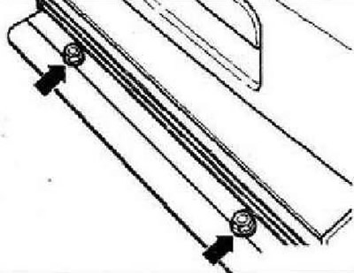
Unscrew the "arrow" screws securing the amplifier. Pull out the amplifier enough to gain access to its connectors.
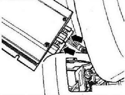
Unlock and disconnect the connectors on the Strelka amplifier. Remove the amplifier.
Installation
When installing, the amplifier must fit properly into the mounting groove. Further assembly is carried out in the reverse order.
The arrangement of contacts in the amplifier connectors
Connector A, 24-pin
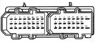
- 1 - High frequency speaker, rear left, positive
- 2 - Low frequency speaker, rear right, minus
- 3 - Subwoofer, rear right, positive
- 4 - Subwoofer, rear left, positive
- 5 - High frequency speaker, rear right, minus
- 6 - High frequency speaker, rear right, positive
- 7 - High frequency speaker, rear left, minus
- 6 - Subwoofer, front left, minus
- 9 - Subwoofer, front left, positive
- 10 - Subwoofer, rear left, minus
- 11 - Midrange speaker, front right, minus
- 12 - Midrange speaker, front right, positive
- 13 - Not used
- 14 - Audio input, rear left channel, minus
- 15 - Audio input, rear left channel, positive
- 16 - Not used
- 17 - Audio input, rear right channel, minus
- 18 - Audio input, rear right channel, positive
- 19 - Control in (optional)
- 20 - Audio input, front left channel, minus
- 21 - Audio input, front left channel, positive
- 22 - Not used
- 23 - Audio input, front right channel, minus
- 24 - Audio input, front right channel, positive
Connector B, 23-pin
- 1 - CAN, low
- 2 - Midrange speaker, front left, minus
- 3 - Midrange speaker, front left, positive
- 4 - SAM, high
- 5 - Not used
- 6 - High frequency speaker, front left, minus
- 7 - Not used
- 8 - Not used
- 9 - High frequency speaker, front left, positive
- 10 - Not used
- 11 - Subwoofer, front right, positive
- 12 - Subwoofer, front right, minus
- 13 - Not used
- 14 - Not used
- 15 - High frequency speaker, front right, positive
- 16 - Power supply, minus
- 17 - Not used
- 18 - High frequency speaker, front right, minus
- 19 - Power supply, minus
- 20 - Power supply, dance
- 21 - Power supply, positive
- 22 - Power supply, minus
- 23 - Power supply, positive
Visitor comments