



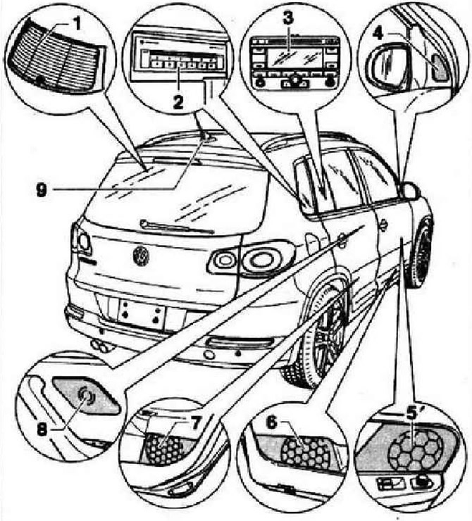
- 1 - Antenna "R11", built into the rear window, for radio reception
- 2 - CD changer "R41" for 6 compact discs, installed under the folding central armrest
- 3 - Control unit with display of the radio navigation system "J503", designation RNS 300
- 4 - Tweeter, front right "R22" and tweeter, front left "R20" are located in the triangular trim of the mirror base on the front right and left doors
- 5 - Midrange speaker, front right "R104" and midrange speaker, front left "R103" are located in the trims of the front left and right doors
- 6 - Front right subwoofer "R23" and front left subwoofer "R21" are located in the front left and right door trims
- 7 - Low frequency speaker, rear right "R17" and low frequency speaker, rear left "R15" are located in the trims of the rear left and right doors
- 8 - High frequency speaker, rear right "R16" and high frequency speaker, rear left "R14" are located in the trims of the rear left and right doors
- 9 - Antenna of the navigation system (GPS) "R50", located at the rear on the roof, for the navigation system
Instructions: The radio navigation system part number is on the sticker on the body of the radio navigation system! When replacing the radio navigation system, be sure to enable coding to make it difficult to use in the event of theft. Be sure to inform the customer of the new code. If the security code is unknown, it can be requested through known systems. When requesting, you must specify the identification number of the radio navigation system. It is on the sticker located on the side of the device. The identification number is duplicated on the side wall of the radio navigation system. When installing a radio navigation system from one car to another, be sure to ensure that the radio navigation systems of both cars have the same part number. Otherwise, there will be malfunctions in the navigation system, since the selsyn sensor setting (steering angle sensor) radio navigation system will not match the car. The radio has a permanent security code that prevents its use in case of theft. When repairing or troubleshooting, use the PAE 5051 tester or VAS 5052 tester or their later modifications in the guided troubleshooting mode. For the navigation system to work correctly, it is necessary to adjust the steering angle sensor (indicate the position of the device relative to the car body). When replacing, install the device with the correct catalog number. Installing another device will cause the navigation system to work incorrectly. After connecting the battery, it is necessary to check the vehicle equipment (radio, clock, electrical equipment of comfort systems). When installing antennas with magnetic mounts on the roof of a car, there is a high probability of interference with the operation of the compass module due to the influence of the magnetic field and the constant magnetization of the roof. In case of complaints about the inaccuracy or incorrect operation of the direction indicator of the compass module, before starting repair work, it is necessary to find out from the customer whether he is using an antenna with a magnetic mount.
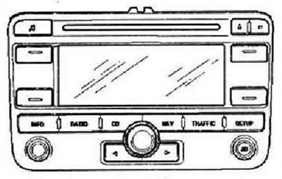
The RNS 300 radio navigation system combines the functions of a navigation system and a high-quality RDS radio. The double-DIN housing of the radio navigation system contains: an RDS radio receiver, a 5.8-inch monochrome display, a navigation system with a GPS receiver, a CD player for audio and navigation systems. The RNS 300 radio navigation system has 4 outputs for connecting speakers. The CD player can read the navigation system CDs or play music CDs. When playing music CDs, the navigation system operates with a limited set of functions.
Instructions: In addition to regular audio CDs, CDs with MP3 files can be played. Playing music CDs with a diameter of cm (minidiscs) impossible. Playback Mix-CD (compact discs containing computer data and music) impossible. To expand the functions, there are connectors for connecting a CD changer and a telephone system. A built-in glass antenna is used to receive the radio signal. A roof-mounted antenna is used to operate the navigation system. The radio antenna is not distributed.
RNS300 Radio Navigation System Connectors
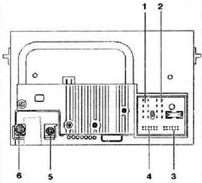
- 1 - 1.8-pin connector
- 2 - 2.8-pin connector
- 3 - 3.12-pin connector
- 4 - 4.12-pin connector
- 5 - Connector 5, navigation system antenna connector
- 6 - Connector 6, radio antenna connector
1.8-pin connector, speaker output
Instructions: When the radio navigation system is equipped with an external amplifier, the signal from these speaker outputs is transmitted to the amplifier.
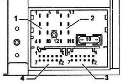
- 1 - Rear right speaker, positive
- 2 - Front right speaker, positive
- 3 - Front left speaker, positive
- 4 - Rear left speaker, positive
- 5 - Rear right speaker, minus
- 6 - Front right speaker, minus
- 7 - Front left speaker, minus
- 8 - Rear left speaker, minus
Connector 2, 8-pin, power supply, CAN bus
- 9 - CAN High Bus
- 10 - CAN Low Bus
- 11 - Muting the radio sound when talking on the phone
- 12 - Power supply, negative, terminal 31
- 13 - Output for turning the radio on/off when the ignition is turned on/off (contact S)
- 14 - Contact for anti-theft alarm
- 15 - Power supply, positive, terminal 30
- 16 - Anti-theft alarm control signal, SAFE
Connector 3, 12-pin, for telephone signals
- 1 - Not used
- 2 - Not used
- 3 - Not used
- 4 - Not used
- 5 - Not used
- 6 - Telephone audio input, TEL-
- 7 - Not used
- 8 - Not used
- 9 - Not used
- 10 - Not used
- 11 - Not used
- 12 - Telephone audio input, TEL+
Connector 4, 12-pin, CD changer control, CD audio signal input
- 1 - Not used
- 2 - CD changer, left and right channels, ground
- 3 - Not used
- 4 - CD changer, power supply, positive, terminal 30
- 5 - Not used
- 6 - CD changer, DATA OUT (data exchange for CD changer control, from radio navigation system to CD changer)
- 7 - Not used
- 8 - CD changer, left channel, CD/L
- 9 - CD changer, right channel, CD/R
- 10 - CD changer, control signal
- 11 - CD changer, DATA IN (data exchange for CD changer control, from CD changer to radio navigation system)
- 12 - CD changer, CLOCK (internal verification protocol for data flow control)
Connectors 5 and 6 for connecting antennas
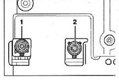
- 1 - Connector with transparent housing - radio antenna input signal (located in the rear window)
- 2 - Blue connector - signal for navigation system from roof antenna
Visitor comments