
IPod jack and related components
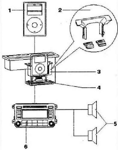
- 1 - iPod player
- 2 - Adapter to adapt the jack to different sized versions of the iPOD player
- 3 - Socket for iPOD player, the socket is built into the stowage compartment under the center armrest
- 4 - Electronic components of the player socket (POD, the socket has a non-separable design, if the electronic components fail, it is replaced as an assembly
- 5 - Left and right speakers in the car, depending on the version of the audio system
- 6 - Radio -R- or radio navigation display control unit -J503-
Installing and removing the socket adapter
Special adapters are available to adapt the jack to different sized iPods. The appropriate adapter for the player being used is inserted into the socket.
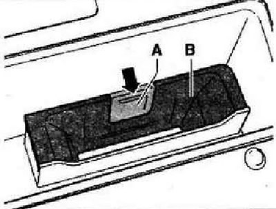
Installation
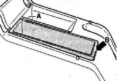
To connect the classic iPod player and the iPod Photo player, proceed as follows. Small adapters are used to compensate for the different thicknesses of the classic iPod and iPod Photo. Insert adapter -A- and adapter -B- in direction -arrow- as far as it will go.
Instruction: There are several versions of the adapter -A-, they differ in thickness.
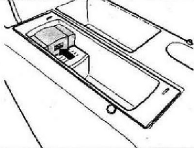
To connect the iPod mini player, proceed as follows:
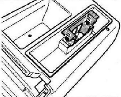
Insert the adapter in the direction of the -arrow- as far as it will go.
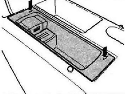
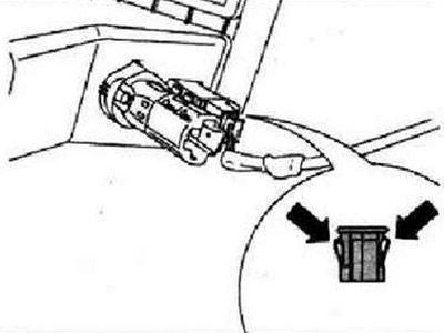
Removing and installing the iPod jack
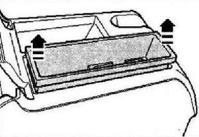
Grasp the inner walls of the storage compartment and pull it outward in the direction of the -arrow-. Disconnect the socket connector at the bottom of the storage compartment.
Installation
Connect connector. Position the storage compartment in the center console first in area -A- and then push it in direction -B- until it locks into place in the center console.
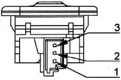
Pin assignment for iPod jack connector
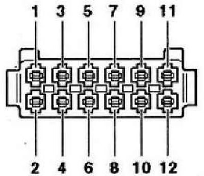
- 1 - DATA (data exchange between iPOD player and radio)
- 2 - DATA-CLOCK (internal verification protocol for data flow control)
- 3 - Power supply, terminal 31, minus
- 4 - Control wire for the radio (as for CD changer)
- 5 - Not used
- 6 - Power supply, plus
- 7 - Audio output, right channel, plus
- 8 - Control wire from the radio, plus (as for CD changer)
- 9 - Audio output, minus
- 10 - Audio output, left channel, plus
- 11 - Not used
- 12 - Not used
USB connector for USB flash drives and MP3 players
The USB port -arrow- is located in the folding armrest. USB connector for connecting USB media (USB flash cards and MP3 players) installed in the Tiguan as an option VW Individual. After connecting a USB stick to the socket, the display of the radio/radio navigation system can show the names of the files contained in its memory. Files can be selected and played through the vehicle's audio system. The power supply of the USB-carrier is made through the USB connector from the vehicle's on-board network.
Supported music file formats
Only files of the following formats can be played: mp3 (MPEG1 Layer 3 32 to 320 kbps), wma (8 to 192 kbps), wav (sample rate 16 kHz with 16-bit encoding, stereo), ogg vorbis (up to q10.48 kHz stereo). DMR files are not supported!
Important notes: Never disconnect media from the USB socket if the source is (CD) USB port is selected. This may damage the media. Do not connect the MP3 player directly to the USB connector - the connector may be damaged. Always use a USB extension cable. Do not connect any other devices to the socket (connect only USB flash drives and MP3 players). Connection of hard drives, hubs and other devices is not provided, they will not work. The maximum amount of power consumed by the USB storage device must not exceed 2.5 W (500mA/5V). Do not connect media with higher power consumption. Do not insert metal objects into the USB port. This may cause a short circuit and damage the device. If the media is not recognized within 15 seconds, you should remove it from the USB connector, and then connect it again. To establish a connection via the USB interface on some models of MP3 players, you must press the corresponding button. The acceptable operating temperature for most USB flash drives and MP3 players is between 0-40°C. Inform the customer that, for this reason, media should not be left in the vehicle for long periods of time.
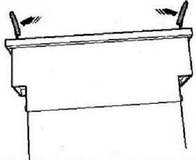
Removing and installing storage compartment with USB connector
A stowage compartment with USB connection is installed in the folding center armrest. Switch off the ignition and all electrical consumers, remove the ignition key. Fully fold out the center armrest. Remove the inserted media/extension cable. Press pullers into grooves -arrows-.
For better understanding, when describing the following operations, the storage compartment is shown removed. Pull the pullers apart -arrows- to release the catches. While holding the pullers pressed against each other, remove the storage compartment from the armrest. Disconnect connector.
Press spring retainer in direction of -arrow- and remove from removed storage compartment in direction of -arrow A-.
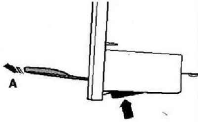
Installation is carried out in the reverse order. Insert the storage compartment into the armrest so that the USB port is at the back.
Location of pins in the USB cable harness connector
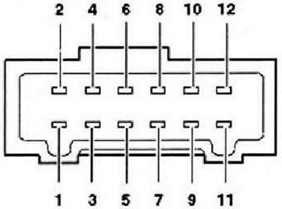
- 1 - Data In, (here is the exit)
- 2 - Data Clock
- 3 - Power supply, terminal 31
- 4 - Data Out, (here is the entrance)
- 5 - Not used
- 6 - Power supply, terminal 30
- 7 - Audio signal NF, right, plus
- 8 - Control wire, plus, is powered by the radio
- 9 - Audio signal NF, minus
- 10 - Audio signal NF, left, plus
- 11 - Not used
- 12 - Not used
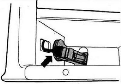
AUX-IN connector
The AUX-IN socket is installed in the center console.
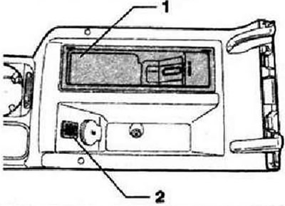
Installation location of the AUX-IN socket -2-.
Location of pins in the connector of the AUX-IN connector assembly
- 1 - Audio signal, left channel
- 2 - Power supply, terminal 31, minus
- 3 - Audio signal, right channel
Removing and installing the AUX-IN connector
If necessary, remove the CD changer. Remove the rear section of the center console. Press retaining clips -arrows- together with wedge -3409- and pull AUX-IN connector out of mounting.
Disconnect connector.
Installation is carried out in the reverse order.
Visitor comments