



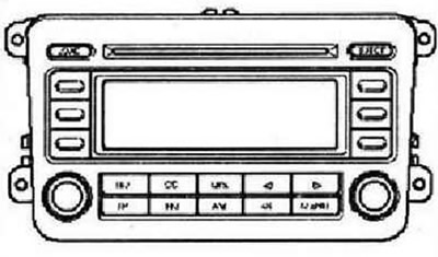
The RCD 500 audio system consists of a radio with an integrated 6-disc CD changer and speakers in the doors. The radio has a built-in amplifier with a power of 4x20 W. The front speakers are 3-way, while 2-way speakers are installed in the rear. There are different versions of the RCD 500 audio system: with speakers connected to 4 channels of the amplifier built into the head unit, or with an external amplifier. In this case, the speakers are connected directly to the external amplifier, and the speaker outputs on the radio are used to transmit the signal to the amplifier. The RCD 500 audio system includes the following speakers: 8 in each front door, one low-frequency, one mid-range and one high-frequency speaker, in each rear door, one low-frequency and one high-frequency speaker. To expand the functions of the external amplifier, there are connectors for supplying a signal to mute the sound during a call and an NF telephone signal input. The built-in 6-disc CD changer can read both regular audio CDs and CD-R and CD-RW discs.
Instructions: An RCD 500 radio can be installed on request in a version capable of playing CDs with MP3 files in addition to regular audio CDs. Playback of music CDs with a diameter of 8 cm (minidiscs) impossible. Playback Mix-CD (compact discs containing computer data and music) impossible. The CD changer of the RCD 500 radio has a transport protection, when installing a new radio, the protection must be disabled. Accordingly, before transporting the removed radio, the transport protection must be enabled. To do this, the power supply must be reconnected to the Ya CD 500 radio. The antenna is built into the rear window. The antenna is spaced.
RCD 500 Radio Connectors
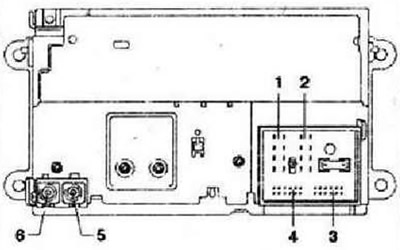
- 1 - Connector 1, 8-pin, speaker output
- 2 - 2.8-pin connector, power supply, CAN bus, phone call mute
- 3 - 3.12-pin connector, telephone signal input
- 4 - 4.12-pin connector, CD changer control, CD audio signal input
- 5 - Connector 5, antenna, beige connector housing, connector for connecting the antenna built into the rear window
- 6 - Connector 6, antenna, connector housing is transparent, connector for connecting the antenna built into the rear window
1.8-pin connector, speaker output
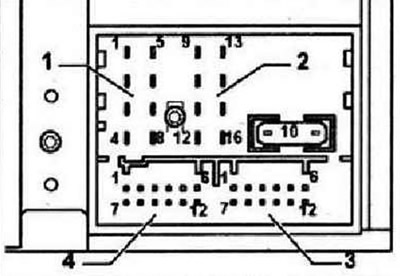
- 1 - Rear right speaker, positive
- 2 - Front right speaker, positive
- 3 - Front left speaker, positive
- 4 - Rear left speaker, positive
- 5 - Rear right speaker, minus
- 6 - Front right speaker, minus
- 7 - Front left speaker, minus
- 8 - Rear left speaker, minus
Connector 2, 8-pin, power supply, CAN bus, phone call mute
- 9 - Can High 10-Can Low
- 11 - Muting the sound when talking on the phone
- 12 - Minus, terminal 31
- 13 - Not used
- 14 - Not used
- 15 - Plus, terminal 30
- 16 - Anti-theft alarm control signal, SAFE
Connector 3, 12-pin, telephone signal input
- 1-5 - Not used
- 6 - Incoming phone signal NF, minus
- 7 - 11 - not used
- 12 - Incoming telephone signal NF, plus
Connector 4, 12-pin, CD changer control, CD audio signal input
- 1 - Headphone output, right, plus
- 2 - CD changer, left and right channels, minus
- 3 - Headphone output, audio signal ground
- 4 - CD changer, power supply, plus
- 5 - Headphone output, left, plus
- 6 - CD changer, DATA OUT bus
- 7 - Not used
- 8 - CD changer, left channel, plus
- 9 - CD changer, right channel, plus
- 10 - CD changer, control signal
- 11 - CD changer, DATA IN bus
- 12 - CD changer, CLOCK bus
Electronic anti-theft system
The radio has a convenient electronic anti-theft protection system that works together with the instrument cluster. When connecting the radio after disconnecting the power, it works without entering a security code. Necessary conditions: the first activation of the electronic anti-theft protection system was carried out, the radio is installed in the same car.
Deactivating the electronic anti-theft system
Re-commissioning of a previously blocked radio is only possible after entering the correct code for the electronic anti-theft system.
Instructions: The electronic anti-theft system code is on the sticker along with the radio number on the radio card. For security reasons, do not keep the radio card in the car. If necessary, ask the customer for the code. If the radio is replaced, use the code for the new radio. Tell the customer the new code. Find out the radio code.
Turn on the radio. The display of the radio will show SAFE, and then: 1000. To enter this mode, you do not need to press any buttons. The position of the entered code is shown on the display next to the four multi-function keys in the form of the symbols _X_. Using the four multi-function keys, enter the code indicated on the sticker of the radio card in the correct sequence. By repeatedly pressing the corresponding keys in turn, achieve the display of the code in the center of the display. Confirm the entry by pressing the multi-function key next to the word ENTER. After this, the radio will be ready for use again, and will work in the same mode as before switching off.
Instructions: If an incorrect number was entered when unlocking, the display will again show a flashing message SAFE, and then 1000. Now you can repeat the process again. The attempt number is displayed on the display. If the code is entered incorrectly again, the device will be locked for about an hour, i.e. it cannot be unlocked during this period of time. The display will show the message SAFE. After an hour (the radio and ignition must remain on, the unlocking attempt indication on the display will disappear, and the electronic lock can be removed in the manner described above. The device operates in a cycle of two unsuccessful attempts, the hourly lock continues.
Visitor comments