



Models produced before 1975
1. Remove the steering column lock as described in previous Section.
2. Remove the small screw and then remove the ignition/starter switch assembly from the lock.
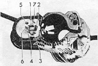
Figure 10.10. Ignition/starter switch - bottom view (refer to the wiring diagram). The arrow indicates the mounting screw: 1 - Contact 30; 2 - Contact 50; 3 - Contact 15; 4 - Contact X; 5 - Contact P; 6 - Contact S; 7 - Contact G.
Models produced since October 1975
3. To remove the ignition/starter switch on these later models, drill a 3.0mm diameter hole in the lock housing as shown in Figure 10.11. This hole will provide access to the cylinder retaining plunger, which must be depressed to release the lock cylinder.
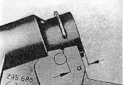
Figure 10.11. Drilling pattern when removing the ignition/starter switch (later models). a = 13.0 mm.
All models
4. Installation is carried out by performing the above steps in reverse order.
The information is posted on this website [www.VWManual.ru]
Visitor comments