



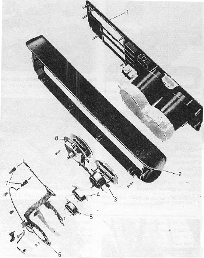
Figure 10.16. Instrument panel without tachometer (Section 20): 1 - Panel; 2 - Overlay; 3 - Clock; 4 - Coolant temperature sensor; 5 - Fuel level sensor; 6 - Printed circuit board; 7 - Light bulbs; 8 - Speedometer.
1. Disconnect the battery and remove the heater control handles (see Fate 20.1).
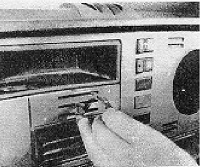
Photo 20.1. Removing the heater control handles.
2. Loosen and remove the four mounting screws from the instrument panel (see photo 20.2).
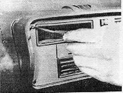
Photo 20.2. Removing the instrument panel screw.
3. Slide the panel forward until you can access the rear of the speedometer and disconnect its cable. If a tachometer is installed, disconnect it in a similar manner (see photo 20.3).
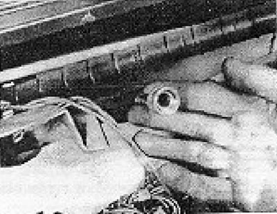
Photo 20.3. Disconnecting the speedometer cable from the speedometer.
4. Disconnect the multi-plug and ground wires.
5 Remove the toolbar (see photo 20.5).
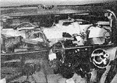
Photo 20.5. Removed instrument panel.
6. Now, if necessary, you can remove individual devices. Take special care not to damage the printed circuit board (see photo 20.6).
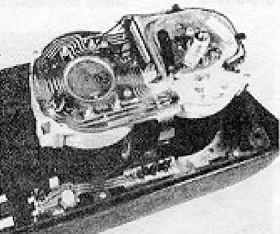
Photo 20.6. Instrument panel rear view.
7. Installation is carried out by performing the above steps in reverse order.
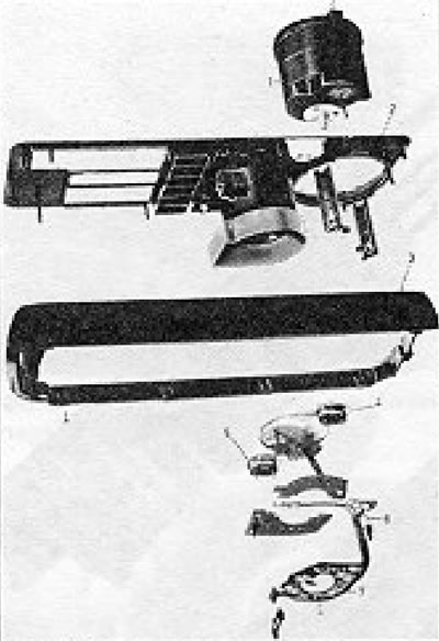
Figure 10.17. Toolbar with tachometer (Section 20): 1 - Tachometer; 2 - Panel; 3 - Overlay; 4 - Coolant temperature sensor; 5 - Fuel level sensor; 6 - Light bulbs; 7 - Printed circuit board.
Visitor comments