
English Русский
Български
Беларускі
Український
Српски
Hrvatski
Română
Polski
Slovenský
Magyar
  |  Articles  |  Sitemap  |  Contacts  |    |
Car maintenance Ford Car maintenance Hyundai Car maintenance Chevrolet Car maintenance BMW Car maintenance Audi Car maintenance Opel Car maintenance AvtoVAZ
VWmanual.ru


Main   Passat   Golf   Polo   Touareg   Tiguan   Sharan   Transporter   Others  
LT 28 (1975-1991) LT 2D (1996-2003) Beetle (1960-1986) Caddy 3 (2003-2010)

Removal and installation the sliding rod (VW Beetle)

  • Main
  • Volkswagen
  • Beetle
  • Transmission
  • Car gearbox
  • Removal and installation the sliding rod
            0


Contents: Removal ↓ Installation ↓

Removal


Raise the vehicle and place it on supports.

Remove the gear shift lever.

Remove the rear seat and the cover of the mounting hole of the tie rod connection on the frame channel.
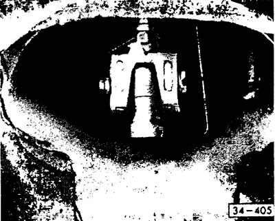
Cut and remove the retaining wire (if any) on the square bolt. Loosen the square bolt using pliers…


Cut and remove the retaining wire (if any) on the square bolt. Loosen the square bolt using pliers or a suitable wrench.

Remove the hex bolt from the tie rod coupling clamp sleeve and remove the coupling.
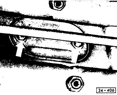
Loosen the bolts on the mounting cover at the front of the frame cross member. The picture shows…


[The original article is available at: VWmanual]

Loosen the bolts on the mounting cover at the front of the frame cross member. The picture shows the cover of the Kafer 1200 car.
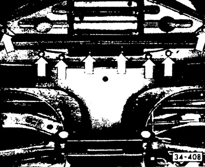
In a car with a long front end (as in this case) a protective stamped element is installed in front…


In a car with a long front end (as in this case) a protective stamped element is installed in front of the frame cross member. To remove it, unscrew all the bolts (see arrows).


Move the rod forward using pliers and remove it. In the case of a vehicle with a long front section, the sliding rod must be rotated for removal and installation.

In the vehicle variant under consideration, remove the guide sleeve with the guide ring from the rod bushing (it can be accessed through the hole in the shift lever in the channel).

Installation


Check all parts for wear and replace if necessary.

Caution! If the sliding rod is knocking, check the bearing bushing and guide ring seat. If the gear shift lever is knocking in the head of the sliding rod, you need to fill the head of the rod with consistent grease.


Lubricate the sliding rod along its entire length with M0S2-based paste and slide it into the frame channel from the front.

Install the bearing sleeve into the stiffening bracket and put on the guide ring.
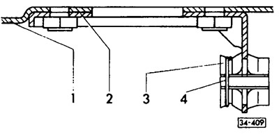
1 - frame tunnel; 2 - amplifier; 3 - bushing; 4 - guide ring

1 - frame tunnel; 2 - amplifier; 3 - bushing; 4 - guide ring


Install the sleeve so that the groove is on the side.

Slide the rod from front to back through the bushing until the rod head is centered in the hole in the frame. At the same time, turn the rod at the front so that it does not get stuck. Install the cover with the seal on the frame cross member and the front protective element.


Install the sliding rod coupling assembly through the mounting hole in the frame channel, install the clamping sleeve and tighten the hex bolt.

Slide the sliding rod connector onto the inner shift lever. Tighten the square bolt.

Attention! The bolt must enter the recess of the sliding rod. Otherwise, there will be difficulties when changing gears. Secure the bolt with wire.


Caution! Self-locking hex bolt (was installed since April 1975, had a length of 10 mm) does not require wire securing. This bolt is for one-time use.


Install the frame cover and tighten the bolts. Put the back seat in place.

Install the gear shift lever.

Adjust gear shifting.

This article is available at russian, bulgarian, belarusian, ukrainian, serbian, croatian, romanian, polish, slovak, hungarian
The text has been checked: Kolesnikov Artem

Share information:

Previous articles
Removal and installation the gear shift lever
Replacing the seals in the axle bearing caps
Replacing the axle shaft covers
Removal and installation the gearbox (with independent wheel suspension)
Replacing the front rubber-metal support
Removal and installation the gearbox (rear axle with diagonal balance beam)
Next articles
Adjusting the gear shift mechanism


Similar articles from other manuals for VW cars:
Cleaning the water drainage hoses of the sliding roof panel Passat B3 (1988-1993)
Removal and installation the glass sliding sunroof cover Golf 4 (1997-2004)
Sliding roof panel: cleaning/lubricating the guide rails Polo 4 (2001-2009)
Sliding door device Transporter T4 (1990-2003)
Link to this page in different formats


Visitor comments


No comments yet


How much will 20 + 11 =


Caddy 3 
  • General information
  • User manual
  • Daily care
  • Maintenance
  • Petrol engines 1.4 l
  • Engine repair
  • Cooling and lubrication system
  • Power and exhaust system
  • Petrol engines 1.6 l
  • Engine repair
  • Cooling and lubrication system
  • Power and exhaust system
  • Diesel engines
  • Engine repair
  • Cooling and lubrication system
  • Power and exhaust system
  • Transmission
  • Mechanical gearbox 0AH
  • Mechanical gearbox 0A4
  • Drive shafts
  • Chassis
  • Car suspension
  • Steering
  • Brake system
  • Body and wiring diagrams
  • Interior and exterior
  • Electrical circuits
Beetle 
  • General information
  • Maintenance
  • Power unit
  • Engine repair
  • Cooling and lubrication system
  • Supply system
  • Exhaust system
  • Transmission
  • Clutch
  • Car gearbox
  • Chassis
  • Front suspension
  • Rear suspension
  • Steering
  • Brake system
  • Wheels and tires
  • Body
  • Exterior
  • Electrical equipment
  • Equipment and devices
  • Power devices
  • Electrical circuits
LT 2D 
  • General information
  • User manual
  • Maintenance
  • Power unit
  • Petrol engines 2.3 l
  • Diesel engines 2.5 l
  • Diesel engines 2.8 l
  • Injection system (diesel 2.8 l)
  • Transmission
  • Clutch
  • Manual gearbox
  • Differential
  • Chassis
  • Car suspension
  • Steering system
  • Brake system
  • Body
  • Body elements
  • Heating system
  • Electrical equipment
  • Equipment and devices
  • Electrical circuits
LT 28 
  • General information
  • Maintenance
  • Power unit
  • Petrol engines 2.0L
  • Petrol engines 2.4L
  • Diesel engines
  • Cooling and heating
  • Fuel and exhaust system
  • Ignition system
  • Transmission
  • Clutch
  • Car gearbox
  • Cardan shaft
  • Rear axle
  • Chassis
  • Brake system
  • Car suspension
  • Steering system
  • Body
  • Body elements
  • Doors, locks and windows
  • Electrical equipment
  • Power devices
  • Equipment and devices
  • Electrical circuits
VWmanual.ru © 2016-2026 | Mobile version | News and articles | Sitemap: EN BG BY UA RS HR RO PL SK HU | Write message | Site search
Passat B2 • Passat B3 • Passat B4 • Passat B5 • Passat B6 • Golf 1, diesel • Golf 1, petrol • Golf 2, petrol • Golf 2 • Golf 3 • Golf 4 • Golf 5 • Polo 3 • Polo 4 • Touareg 1 • Tiguan 1 • Sharan 1 • Transporter T3 • Transporter T4 • LT 28 • LT 2D • Beetle • Caddy 3 •
Our website uses cookies to ensure functionality and convenience.