



The PBS prevents the wheels from locking during sudden braking. The braking distance is reduced, since the force closure between the wheels and the road surface is greater if the wheels rotate during braking. In addition, the car remains controllable.
The PBS is designed as a three-chain device. This means that the front wheels are controlled independently of each other. The rear wheels are controlled together, with control determined by the wheel that is more prone to locking.
The PBS is ready for action after the ignition is turned on and the speed reaches 5-7 km/h. It affects the braking processes as soon as the speed reaches 12 km/h.
The speed of rotation of the wheels is measured by means of speed sensors on all four wheels. By processing the signals from the individual sensors, the control unit calculates an average speed, which approximately corresponds to the speed of the vehicle. By comparing the speed of rotation of the individual wheels with the average speed, the control unit determines the degree of slippage of the individual wheels and can thus determine the moment when one of the wheels is about to lock.
(The original text is available on the portal: vwmanual)
As soon as one of the wheels approaches locking, the brake fluid pressure in the brake pad or brake cylinder becomes too high in relation to the tire grip on the road, and the hydraulic system, under the influence of signals from the control unit, keeps the brake fluid pressure stable. This means that the pressure in the brake cylinders does not increase even if the brake pedal is pressed further. If the risk of locking remains, the pressure is reduced by opening the release valve, but only to a level where the wheel begins to rotate slightly again, after which the pressure is again kept stable.
If the wheel starts to spin faster to a certain extent, the hydraulic system increases the pressure, but not above the total pressure in the brake system.
This process is repeated during hard braking for each braking circuit until the brake pedal is released or the vehicle speed is reduced to 2-3 km/h.
The safety circuit of the electronic control device ensures that the PBS, in the event of a malfunction, (for example, a cable break) or if the battery voltage is too low (below 10.5 volts) switched off automatically. In this case, the PBS control signal lights up on the instrument panel while driving.
If the anti-lock braking system indicator light comes on while driving, this indicates that the anti-lock braking system has been deactivated.
- stop the car, turn off and start the engine again.
- check the battery voltage. If it is below 10.5 volts, charge the battery.
Attention! If the PBS control signal lights up at the beginning of the ride and goes out again after some time, this indicates that the battery voltage was too low, but then increased due to recharging from the generator.
- check the strength of the terminal connection to the battery.
- lift the car, remove the front wheels, check the electrical wires for external damage (grinding).
- further checking should be entrusted to a workshop.
Attention! Before welding with electric welding, disconnect the plug from the control device. Disconnect the plug only when the ignition is switched off. When varnishing, the control device may be exposed to short-term temperatures not exceeding 95 degrees C or to long-term (about 2 hours)up to 85 degrees.
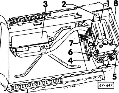
(1) hydraulic block
(2) relay
(3) control device
(4-8) brake wires
(47-447) The electronic control unit and hydraulic unit are built under the driver's seat.
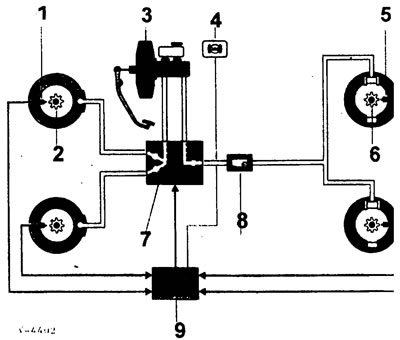
(1) RPM sensor (front)
(2) impulse wheel
(3) brake booster
(4) PBS control lamp
(5) RPM sensor (rear)
(6) Impulse wheel
(7) hydraulic block
(8) Brake force regulator
(9) control device
Visitor comments