



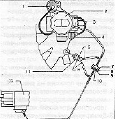
Figure 13.45. Schematic diagram of the engine vacuum system (section 7): 1 - Vacuum block, chamber 2; 2 - Carburetor 2B6; 3 - Identification color: black; 4 - Air damper lowering block; 5 - Gray; 6 - Red; 7 - White; 8 - Brown; 9 - Black; 10 - Damping valve (pay attention to the position of the installed valve); 11 - Thermopneumatic valve; 12 - Distributor.
44. The vacuum regulator consists of a damping valve and a thermopneumatic valve.
45. The damper valve allows all air flow from the distributor to the carburetor, but restricts flow in the opposite direction.
46. Please note that the valve should be with the dark side facing the distributor.
47. The thermopneumatic valve is screwed into the intake manifold.
48. At temperatures above 46°C the valve is open and does not impede the air flow; at temperatures below 30°C it closes. That is, at temperatures above 30°C, this valve acts as a bypass channel in relation to the damping valve.
49. This design ensures better starting and operation of a cold engine.
50. It is best to check the O6a valves by trial replacement.
Visitor comments