



5 Remove the runner (see photo).
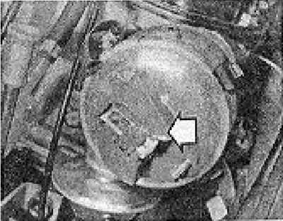
Photo 7.5. Distributor rotor (shown by the arrow).
6. Remove the waterproof cover (see photo).
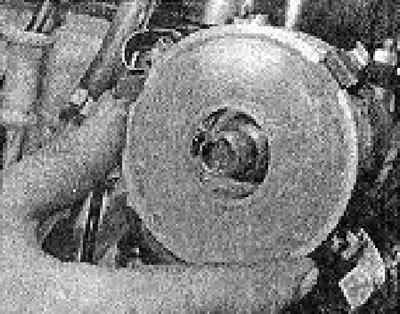
Photo 7.6. Removing the moisture-proof cover.
7. Disconnect the low voltage wire.
8. Remove the screw securing the contacts to the distributor support plate (see photo).
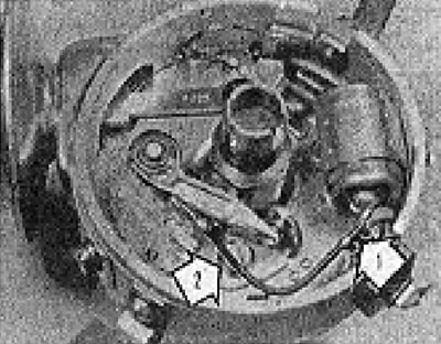
Photo 7.8. Breaker contacts: 1 - Low voltage wire connection point; 2 - Mounting screw.
9. Install new contacts in reverse order, without fully tightening the mounting screw yet.
10. Turn the engine so that the back side of the movable contact is on the top point of one of the ledges of the distributor cam.
11. Using feeler gauges and moving the fixed contact with a screwdriver inserted into the slot on the contact and resting on the head of one of the two rivets, achieve the required gap size between the contacts (see Specifications for Chapter 4).
12. This adjustment is basic and at the first opportunity you should adjust the ignition timing based on the angle of the closed state of the contacts.
13. Tighten the contact fastening shaft completely.
14. Install the moisture-proof cover.
15. Install the runner.
16. Install the distributor cap.
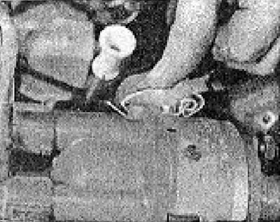
Photo 7.16. Distributor cover fastening clamps.
Visitor comments