
English Русский
Български
Беларускі
Український
Српски
Hrvatski
Română
Polski
Slovenský
Magyar
  |  Articles  |  Sitemap  |  Contacts  |    |
Car maintenance Ford Car maintenance Hyundai Car maintenance Chevrolet Car maintenance BMW Car maintenance Audi Car maintenance Opel Car maintenance AvtoVAZ
VWmanual.ru


Main   Passat   Golf   Polo   Touareg   Tiguan   Sharan   Transporter   Others  
LT 28 (1975-1991) LT 2D (1996-2003) Beetle (1960-1986) Caddy 3 (2003-2010)

Van sliding door — removal, disassembly, assembly and adjustment (VW Lt 28)

  • Main
  • Volkswagen
  • LT 28
  • Body
  • Doors, locks and windows
  • Van sliding door — removal, disassembly, assembly and adjustment
            0


1. Remove the sliding door guide rail cover as described in Section 2.

2. Bring the door to the open position until it is possible to lift the hinge guide from the opening in the guide rail.
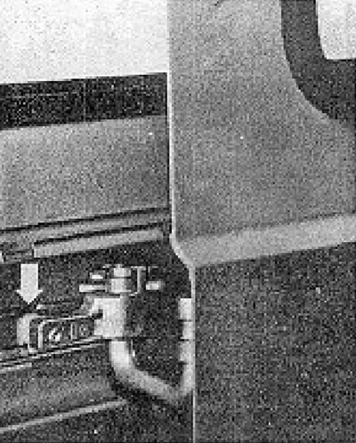
Figure 12.58. Part of the guide hinge of a sliding door (indicated by the arrow).

Figure 12.58. Part of the guide hinge of a sliding door (indicated by the arrow).


3. Open the door fully and release the top roller from its guide.
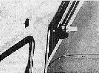
Figure 12.59. Upper roller of the sliding door guide (indicated by the arrow).

Figure 12.59. Upper roller of the sliding door guide (indicated by the arrow).


4. Slide the door outward slightly and release the lower roller from the opening in the guide rail.
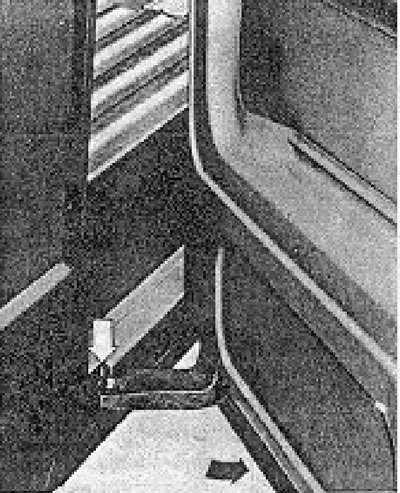
Figure 12.60. Bottom roller of the sliding door guide (indicated by the arrow).

Figure 12.60. Bottom roller of the sliding door guide (indicated by the arrow).


5. The lock plate can be removed after unscrewing the two mounting bolts.
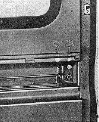
Figure 12.61. Sliding door lock plate mounting screws.

Figure 12.61. Sliding door lock plate mounting screws.


6. The connecting hinge can be unscrewed and removed from the door opening to replace any worn parts.
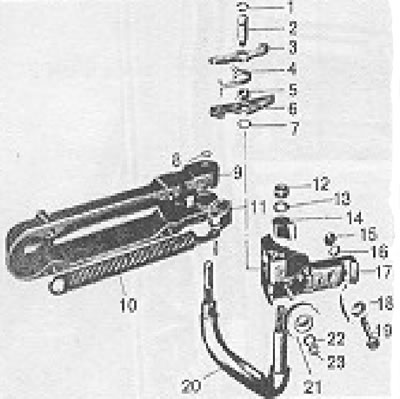
Figure 12.62. Components of a sliding door hinge: 1 - Spring clamp; 2 - Pin; 3 - Locking lever; 4 -…

Figure 12.62. Components of a sliding door hinge: 1 - Spring clamp; 2 - Pin; 3 - Locking lever; 4 - Spring; 5 - Gasket sleeve; 6 - Locking lever; 7 - Washer; 8 - Spring clamp; 9 - Casing; 10 - Spring; 11 - Spring mount; 12 - Nut; 13 - Spring washer; 14 - Operating cam; 15 - Nut; 16 - Spring washer; 17 - Loop fastening; 18 - Guide; 19 - Screw; 20 - Linking loops; 21 - Roller; 22 - Spring washer; 23 - Nut.


7. Assembly is carried out by performing the above steps in reverse order. Before installation, lubricate the connecting loops.


8. Installation on site is also carried out by performing the above steps in reverse order, but it is necessary to make adjustments so that there is an equal gap with the adjacent body panels along the entire perimeter of the door when the door is in the closed position. The door mod should be aligned with the body molding, and the entire door surface should be flush with the adjacent body panels.

9. If the top edge of the door does not fit into place properly, adjust the height of the top roller so that the minimum possible gap remains between the roller and the guide. The position of the roller can also be adjusted using its bracket.
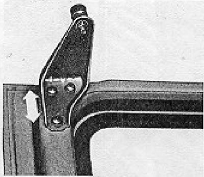
Figure 12.64. Adjusting the top roller of a sliding door.

Figure 12.64. Adjusting the top roller of a sliding door.


10. If the front edge of the door does not fit properly and align with the body panel, adjust the position of the lower guide roller. Do this by removing the Phillips screw on the front edge of the door and the two bolts underneath it. Vertical adjustment (height) is made by inserting washers as shown at point A (see Figure 12.65).
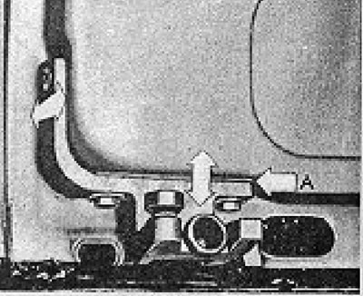
Figure 12.65. Adjusting the lower roller of the sliding door.A - Gasket location.

Figure 12.65. Adjusting the lower roller of the sliding door.A - Gasket location.


11. Adjustment of the rear edge of the sliding door is made by changing the position of the plate of the counter part of the lock.
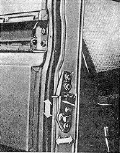
Figure 12.66. Door latch counter plate. The arrows indicate the adjustment limits.

Figure 12.66. Door latch counter plate. The arrows indicate the adjustment limits.


If this is done, the binding loop can also be adjusted (see point 13), as well as the latch protrusion on the inner handle.

12. The counter plate of the lock can be released by slightly loosening its mounting screws. Close the sliding door from the inside, this will center the counter plate. Tighten the top plate bolt before opening the door, then open the door and tighten the second bolt. If necessary, washers can be installed under the plate to increase its protrusion.

13. To adjust the hinge link, close the door and, working from the inside, loosen the four hinge mounting bolts.
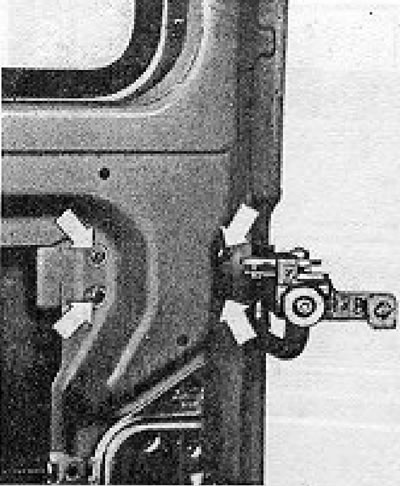
Figure 12.63. Mounting screws for the connecting hinge of a sliding door.

Figure 12.63. Mounting screws for the connecting hinge of a sliding door.


14. Have an assistant pull the binding loop down until the roller and guide portion come into contact with the guide rail. Retighten the four bolts.

This article is available at russian, bulgarian, belarusian, ukrainian, serbian, croatian, romanian, polish, slovak, hungarian
The text has been checked: Kolesnikov Artem

Share information:

Previous articles
Van sliding door central locking — removal and installation
Van sliding door lock — removal, installation and adjustment
High-roof van secondary rear door lock — removal, installation and adjustment
High-roof van rear door primary lock — removal, installation and adjustment
Secondary lock for the rear door of a high van — removal, installation and adjustment
Primary lock of the rear door of a high van — removal and installation
Next articles


Similar articles from other manuals for VW cars:
Removal and installation / adjustment of the door Passat B3 (1988-1993)
Engine adjustment data Golf 1 (1974-1984, petrol)
Removal and installation/adjustment of the rear door Polo 4 (2001-2009)
Door adjustment Touareg 1 (2002-2006)
Door adjustment Tiguan 1 (2007-2015)
Knock sensor. Knock adjustment Sharan 1 (1995-2000)
Sliding door adjustment Transporter T3 (1979-1992)
Link to this page in different formats


Visitor comments


No comments yet


How much will 34 + 42 =


Caddy 3 
  • General information
  • User manual
  • Daily care
  • Maintenance
  • Petrol engines 1.4 l
  • Engine repair
  • Cooling and lubrication system
  • Power and exhaust system
  • Petrol engines 1.6 l
  • Engine repair
  • Cooling and lubrication system
  • Power and exhaust system
  • Diesel engines
  • Engine repair
  • Cooling and lubrication system
  • Power and exhaust system
  • Transmission
  • Mechanical gearbox 0AH
  • Mechanical gearbox 0A4
  • Drive shafts
  • Chassis
  • Car suspension
  • Steering
  • Brake system
  • Body and wiring diagrams
  • Interior and exterior
  • Electrical circuits
Beetle 
  • General information
  • Maintenance
  • Power unit
  • Engine repair
  • Cooling and lubrication system
  • Supply system
  • Exhaust system
  • Transmission
  • Clutch
  • Car gearbox
  • Chassis
  • Front suspension
  • Rear suspension
  • Steering
  • Brake system
  • Wheels and tires
  • Body
  • Exterior
  • Electrical equipment
  • Equipment and devices
  • Power devices
  • Electrical circuits
LT 2D 
  • General information
  • User manual
  • Maintenance
  • Power unit
  • Petrol engines 2.3 l
  • Diesel engines 2.5 l
  • Diesel engines 2.8 l
  • Injection system (diesel 2.8 l)
  • Transmission
  • Clutch
  • Manual gearbox
  • Differential
  • Chassis
  • Car suspension
  • Steering system
  • Brake system
  • Body
  • Body elements
  • Heating system
  • Electrical equipment
  • Equipment and devices
  • Electrical circuits
LT 28 
  • General information
  • Maintenance
  • Power unit
  • Petrol engines 2.0L
  • Petrol engines 2.4L
  • Diesel engines
  • Cooling and heating
  • Fuel and exhaust system
  • Ignition system
  • Transmission
  • Clutch
  • Car gearbox
  • Cardan shaft
  • Rear axle
  • Chassis
  • Brake system
  • Car suspension
  • Steering system
  • Body
  • Body elements
  • Doors, locks and windows
  • Electrical equipment
  • Power devices
  • Equipment and devices
  • Electrical circuits
VWmanual.ru © 2016-2026 | Mobile version | News and articles | Sitemap: EN BG BY UA RS HR RO PL SK HU | Write message | Site search
Passat B2 • Passat B3 • Passat B4 • Passat B5 • Passat B6 • Golf 1, diesel • Golf 1, petrol • Golf 2, petrol • Golf 2 • Golf 3 • Golf 4 • Golf 5 • Polo 3 • Polo 4 • Touareg 1 • Tiguan 1 • Sharan 1 • Transporter T3 • Transporter T4 • LT 28 • LT 2D • Beetle • Caddy 3 •
Our website uses cookies to ensure functionality and convenience.