



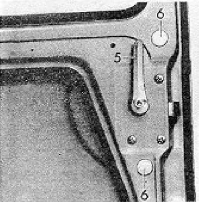
Figure 12.42. High roof van rear door lock handle (5) and plugs (6) (Section 15).
2. Remove the plugs and screws visible through the holes in the door panel to release the locking rods.
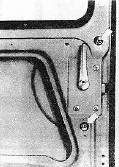
Figure 12.43. Latch clamp screws visible through door panel holes (Section 15).
3. Remove the lower locking rod from the door in a downward direction.
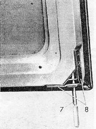
Figure 12.44. Removing the lower locking rod (Section 15): 7 - Locking rod; 8 - Rod guide.
4. Remove the upper locking rod guide and remove the rod from the door.
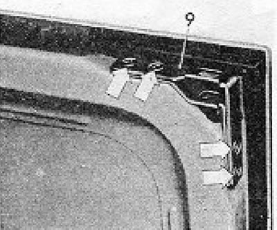
Figure 12.45. Upper rod guide (9). The mounting screws are indicated by arrows (Section 15).
5. Remove the mounting screw from the inner handle and remove it.
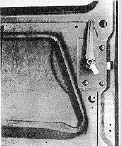
Figure 12.46. Inner handle mounting screw (Section 15).
6. Unscrew the three screws and remove the lock from the door opening.
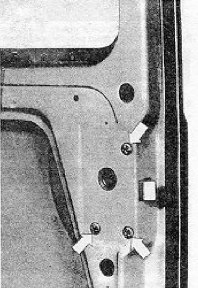
Figure 12.47. Lock mounting screws (Section 15).
[View the original on the website VWmanual]
7. Installation on mine is carried out by performing the above steps in reverse order, however, before tightening the screws of the locking rod clamps, make the following adjustment.
8. Check that the rods are in the unlocked position.
9. The top rod is installed correctly when the high end of the projection is flush with the surface of the rod guide plate.
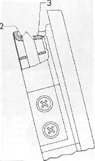
Figure 12.48. Upper locking rod installation diagram (Section 15): 2 - Protrusion in the unlocked position; 3 - Surface of the rod guide.
Only turn the lug a whole number of turns, and when finished, make sure the rod knee is facing the correct direction.
10. The bottom rod is installed correctly when the high end of the ledge is flush with the surface of the guide tongue.
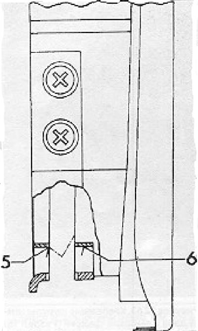
Figure 12.49. Lower locking rod installation diagram (Section 15): 5 - Latch in unlocked position; 6 - Guide tongue.
Visitor comments