



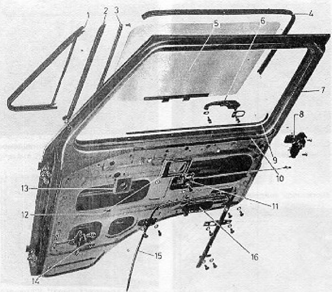
Figure 12.18. Front Door Components (Section 9): 1 - Small fixed glass seal; 2 - Glass guide; 3 - Door seal; 4 - Glass guide; 5 - Glass; 6 - Outside door handle; 7 - Door frame; 8 - Door lock; 9 - External seal; 10 - Inner seal; 11 - Lever; 12 - Gasket; 13 - Gasket; 14 - Door stopper; 15 - Window lift mechanism; 16 - Ventilation hole.
1. Remove the inner door trim panel as described above.
2. Lower the glass down so that it can be detached after unscrewing the two bolts. Roll down the window.
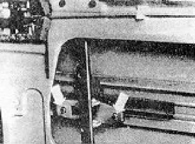
Figure 12.17. Bolts securing the glass to the window regulator (Section 9).
3. Remove the glass seal channel back and unscrew the screws securing the upper part of the glass guide.
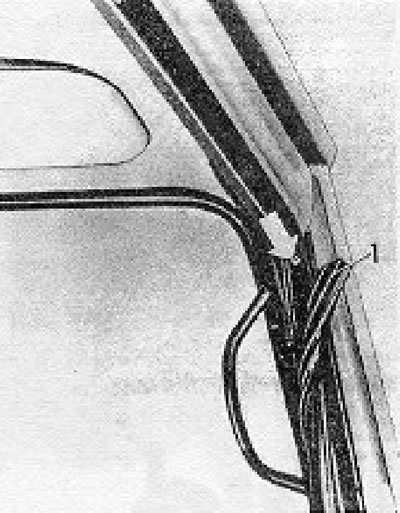
Figure 12.19. Glass guide mounting screw (indicated by the arrow) (Section 9); 1 - Gasket.
4. Loosen the bolt that secures the lower part of the glass guide and remove the guide and seal towards the rear.
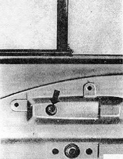
Figure 19.20. Upper glass guide mounting bolt (Section 9).
5. Remove the inner and outer window seals from their mounting clips.
6. Remove the small fixed glass and its seal.
7. Lift the glass with your hand and remove it from the door by tilting and turning it.
8. Unscrew the window lift mechanism bolts, bend back the metal tab and remove the mechanism (see photo 9.8).
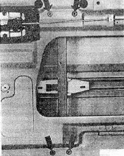
Figure 12.21. Upper window lift mechanism bolts (Section 9).
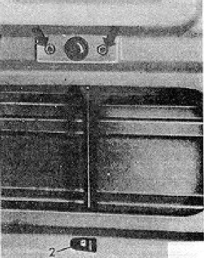
Figure 12.22. Lower window regulator bolts (indicated by arrows) (Section 9); 2 - Metal protrusion.
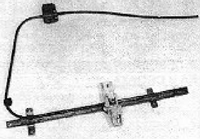
Photo 9.8. Window lift mechanism.
9. The outer door handle can be removed after unscrewing two screws.
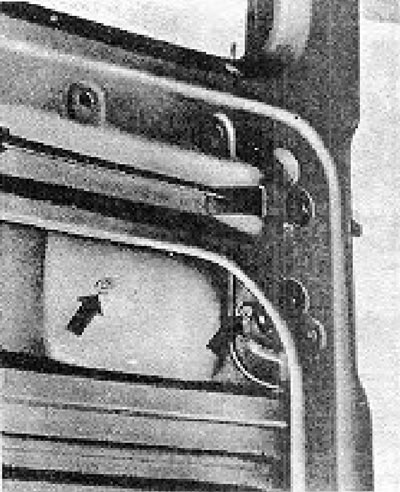
Figure 12.23. External door handle mounting screws.
10. Disconnect the spring (3) from the lever (4) (see Figure 12.24).
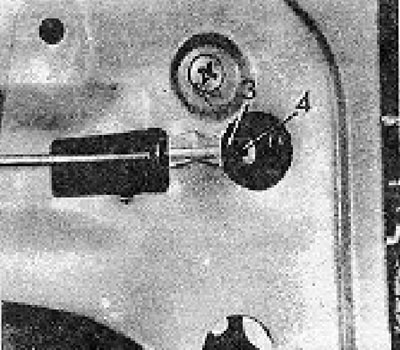
Figure 12.24. Lock lever (Section 9): 3 - Spring; 4 - Control lever.
Loosen the lever mounting screws and remove the entire structure (see photo 9.10).
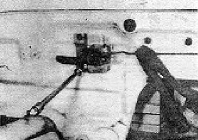
Photo 9.10. Removing the lock handle screw.
11. The door lock can be removed from the door opening after unscrewing the mounting screws from the edge of the door (see Figure 12.25).
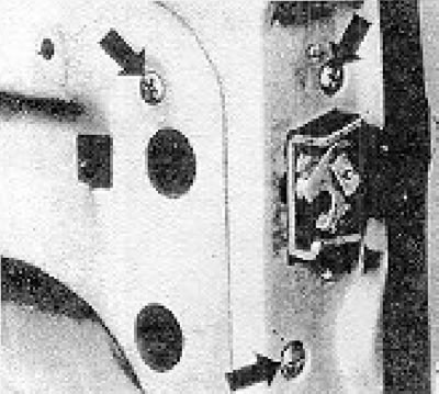
Figure 12.25. Door lock mounting screws (Section 9).
12. Installation is carried out by performing the above steps in reverse order, however, before tightening the bolts securing the glass to the window lift mechanism, fully raise the glass so that it fits into the guides. The inside door panel is provided with holes to fully tighten the window regulator bolts when the window is in the fully raised position.
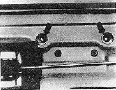
Figure 12.26. Window lift mechanism mounting bolts - view through special access holes (Section 9).
Visitor comments