
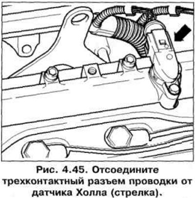
1. Disconnect the three-pin wiring connector from the Hall sensor (arrow) (pic. 4.45).
2. Connect the multimeter using wires from VAG 1594 to the outer contacts of the wiring connectors (rice. 3.44).
3. Turn on the ignition. Specification value: min. 9 V.
4. Turn off the ignition.
5. Connect a multimeter to measure voltage using wires from the VAG 1594 tester to pins 1 (positive pole) and 3 («weight») crankshaft speed sensor wiring connector (rice. 4.39).
6. Turn on the ignition. Specification value: 4.5 V.
7. Turn off the ignition.
8. If there is no voltage, remove the cover on the left in the engine compartment and connect the VAG 1598/31 tester to the engine control unit wiring harness (on the left side of the engine compartment) (rice. 4.32). The control unit must remain disconnected.
9. Check the wires between the tester and the connector for continuity: pin 1 + socket 98, pin 2 + socket 86, pin 3 + socket 108. Wire resistance: max. 1.5 ohm.
10. In addition check up short circuit one on another wires.
Specification resistance: ∞ Ohm.
11. If no faults are found in the wiring and there is voltage between pins 1 and 3, replace the Hall sensor.
12. If no faults are found and there is no voltage between pins 1 and 3, replace the engine control unit.
Visitor comments