



Power supply to most consumers is supplied via the ignition switch. The power supply circuits of those electrical equipment units whose operation may be required under any circumstances are always connected to the battery, regardless of the position of the key in the ignition switch.
Electrical connectors with flat contacts are used to connect wires.
For normal power supply of consumers, the electric circuit must be closed, since otherwise there will be no electric current in it, for example, if a positive voltage is supplied to the windshield wiper motor, it will not work until its electric circuit is connected to the ground. Switches, relays, fuses, measuring devices, electric motors and other consumers of electric power can be connected to the electric circuit. For the correct connection of consumers of electric power, the contacts of electrical connectors have the appropriate markings. To simplify the use of the electrical circuit, individual electrical circuits are located vertically and numbered. The lower line in the diagram is the car ground. The connection to the car ground is carried out either directly through the body of the consumer of electric power or by an additional wire. Under the lower line of the ground on the electrical circuits there are coordinates by which, using a key, you can determine the electrical circuit or element.
The numbers on the electrical diagram in the black rectangles at the end of the wire show the coordinate at which it continues. There is also a return reference at this coordinate.
When working with an electrical circuit, it is necessary to know the letter and graphic designation of electrical elements.
Decoding the letter designation of elements
| A | battery |
| IN | starter |
| WITH | generator |
| D | ignition switch |
| E | switch |
| F | mechanical switch |
| G | sensor, measuring device |
| N | sound signal |
| J | relay |
| K, L, M, W, X | lamps, control lamps |
| N | electromagnetic valves, resistors, switches |
| ABOUT | distributor |
| R, Q | spark plugs |
| R | radio |
| S | fuses |
| T | electrical connectors |
| V | electric motors |
There is a digital designation next to the letter designation.
Relays and control units are framed to identify them. The lines inside the frame represent the internal connections in the unit.
The white number in the black square indicates the relay number on the relay block. The numbers next to the relay indicate the relay contact numbers, for example, the designation 17/87 indicates that the number 17 is the contact designation on the board, and the number 87 is the relay contact designation.
Contact 30. Positive battery voltage is always present on this contact. The wires connected to this contact are red or red with a stripe.
Contact 31. The contact is connected to the vehicle ground with a brown wire.
Contact 15. Positive voltage is supplied to this contact after the ignition is turned on. The wires connected to this contact are green or green with a stripe.
Contact X. Voltage is supplied to the contact after the ignition is turned on, but when the starter is turned on, the voltage is disconnected. This makes it possible to turn off unnecessary consumers of electricity at this moment when starting the engine. The high beam headlights also receive power from this contact, so when the high beam is on and the ignition is turned off, an automatic switch to the parking lights occurs.
The wires are designated by numbers and letters located underneath them.
The numbers indicate the cross-section of the conductor in mm², and the letters indicate its color. If the wire color designation contains several groups of letters, the first group of letters indicates the main color of the wire, and the second - the color of the strip.
(The text is copied from this portal: vwmanual)
On wire harnesses connected by a single- or multi-pin connector, a combination of numbers is added to the letter "T".
For example:
- T2p = two-pin connector;
- E32/27 = 32 pin connector with connection point 27.
In the diagram, all current consumers and switches are shown in the neutral position. The changed current characteristic after the action on the switch is interpreted using the example of a two-stage switch.
Electrical diagram of the switch
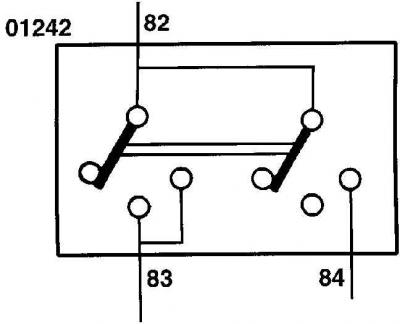
When the switch is turned to the first position, current flows from contact 82 to contact 83. The second section of the switch is also set to the middle position, but the contacts are not closed. Only when the switch is turned to the second position, current begins to flow from contact 82 to contact 84 and then enters the circuit. At the same time, due to the internal connection, current also continues to flow from contact 82 to contact 83.
Warning: The fuse marked #24 on the fuse box is marked #224 on the vehicle's electrical diagrams, which means the fuse number is preceded by a 2 on the electrical diagrams.
Visitor comments