
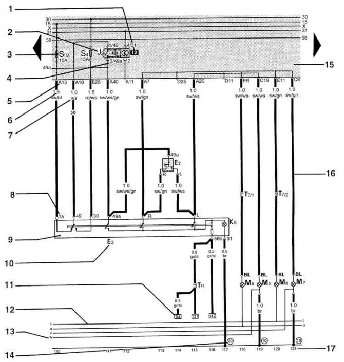
- 1 - the location of the relay. The number 12 indicates the location of the relay on the block.
- 2 - block or element designation. The block or element designation is given in the specification.
- 3 - designation of the fuse. For example: Fuse 19 with a protection current of 10 A.
- 4 - designation of contacts. For example: Contact 3/49a. 3 - contact 3 of relay 12 on the relay block.
- 5 - designation of contacts on the relay block. A13 stands for pin 13 of connector A.
- 6 - wire section in mm2.
- 7 - wire color. Wire colors are shown in the wiring diagrams.
- 8 - contact designation.
- 9 - block or element.
- 10 - Designation of the block or element and its number.
- 11 - continuation of the wiring. The number in the rectangle indicates the electrical circuit to which this wire is connected.
- 12 - internal connections.
- 13 - continuation of the wiring of the internal connection.
- 14 - designation of the grounding point.
- 15 - relay and fuse block.
- 16 - external connections.
- 17 - numbers of coordinates. Designed to facilitate the search for nodes in the diagrams.
Visitor comments