



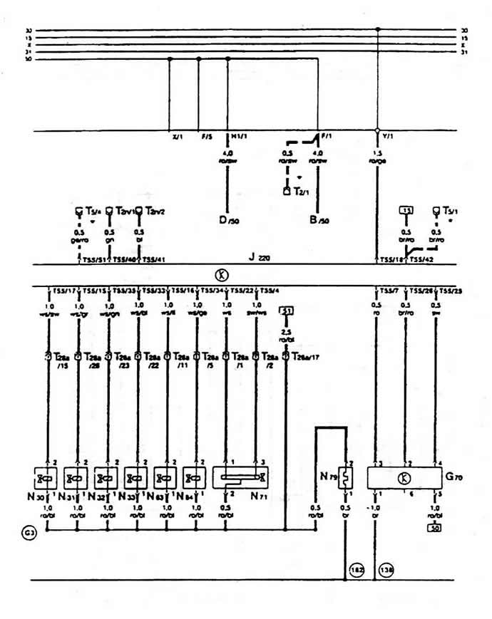
- F87 - thermal switch for fan inertia
- G2 - coolant temperature sensor
- G3 - long-range thermometer
- G5 - tachometer
- J138 - Fan Inertia Control Device
- J220 - "Motronic" control unit
- J252 - Oil pressure and coolant warning indicator control unit
- J27 - continuous circulation cooling system blocking diode, above the relay box
- J271 - Current relay for installation "Monotronic"
- N80 - valve with control by means of a retracting magnet, for a container with activated carbon
- T1p - single plug, behind the relay box
- T1s - single plug, behind the relay box
- N3 - triple plug, near the battery
- T5 - 5-pole plug, above the relay box
- T28 - 28-pin plug, to cylinder head, left
- T28 - 28-pin plug, to removable instrument cluster
- V51 - coolant circulation pump
Connection points with the body (in circle):
- 15 - ground point, to the cylinder head
- 137 - connection of "mass" (output stage). in the injection device cable
- 138 - connection of "mass" (electronics), in the injection device cable
- 182 - ground connection 1, in the injection device cable
- C11 - connection in the cooling fan cable
- E7 - positive connection (87a), in the injection device cable
* Only with automatic transmission
Cable color designations:
- ws - white
- sw - black
- ro - red
- br - brown
- gn - green
- gr - gray
- li - purple
- ge - yellow
- bl - blue
List of fuses:
- 30A - green color
- 25A - white
- 20A - yellow
- 15A - blue
- 10A - red
Visitor comments