
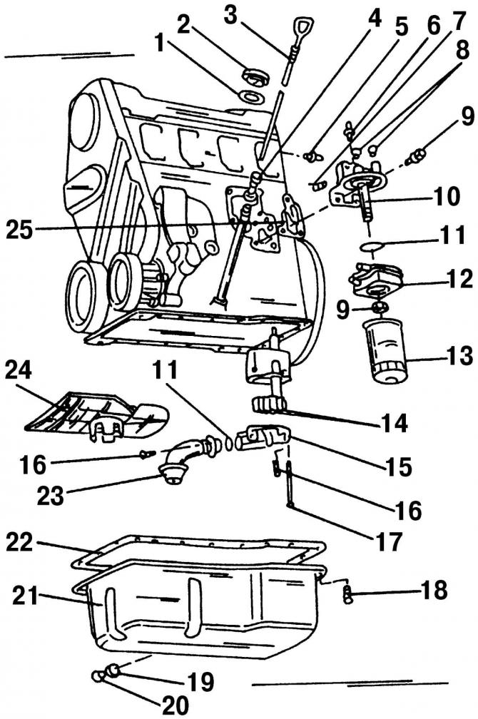
Pic. 166. Lubrication system of a 2.0-liter engine: 1 - gasket, replace with a new one; 2 - oil filler cap; 3 - dipstick for checking the oil level; 4 - dipstick guide tube for checking the oil level; 5 - oil pressure switch at 25 kPa; 6 - oil pressure switch at 180 kPa; 7 - check valve, 5 Nm; 8 - plugs; 9 - nut, 25 Nm; 10 - base of the oil filter; 11 - O-ring, always replaceable; 12 - oil cooler; 13 - oil filter; 14 - oil pump gear; 15 - oil pump cover with pressure reducing valve; 16 - bolt, 10 Nm; 17 - bolt, 20 Nm; 18 - oil sump mounting bolt; 19 - sealing ring, replace; 20 - oil drain plug; 21 - oil pan; 22 - gasket, replace with a new one; 23 - oil receiver; 24 - oil guide plate; 25 - gasket, replace with a new one
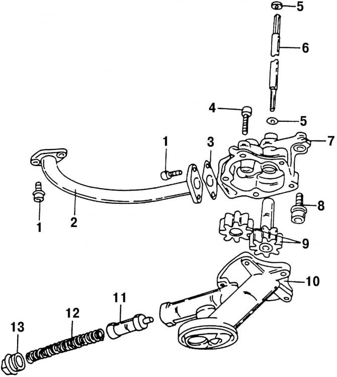
Pic. 170. Oil pump disassembled (VR6): 1 - bolt, always a replacement; 2 - oil receiver pipe; 3 - gasket, always a replacement; 4 - bolt, 10 Nm; 5 - O-ring, always a replacement; 6 - pump drive shaft; 7 - oil pump housing; 8 - a bolt with an internal hexagon, 25 Nm; 9 - gears of the oil pump; 10 - oil pump cover with pressure reducing valve; 11 - damper of the pressure reducing valve; 12 - spring; 13 - screw cap of the pressure reducing valve, 40 Nm
In the event of a breakdown, the oil pump is in most cases replaced with a new one. However, it can be taken apart to check and determine how worn its parts are. Since the oil pressure in the oil pump is generated by the rotation of interlocking gears, in most cases it is possible to repair the pump by replacing these gears, provided that the pump housing itself is not damaged. There is a pressure reducing valve in the pump cover, which may be the cause of the malfunction. To disassemble the pump, depending on the type of engine, follow either fig. 166 (engine 2.0 l), or Fig. 170 (VR6 engine).
Disassemble the oil pump in the following order:
- unscrew the mounting bolts from the bottom and top of the pump housing and remove the pump cover from the pump housing. On a 2.0-liter engine, remove the two short bolts from the pump cover;
- unscrew two bolts 1 (pic. 170) fasteners and remove the oil receiver together with the gasket 3 from the body 7 of the oil pump of the VR6 engine. The 2.0 liter engine uses an O-ring 11 (pic. 166). The gasket or O-ring must be replaced with a new one;
- unscrew the mounting bolts and remove the pump cover 10 (pic. 170) with pressure reducing valve from body 7;
- remove the gear wheel with the shaft and the gear wheel without the shaft from the pump housing 9;
- pull out the drive shaft 6 of the oil pump. The drive shaft has two O-rings 5 (only for VR6 engine), which should always be replaced with new ones.
Checking the technical condition of the oil pump parts
After dismantling, wash all parts with detergents, blow with compressed air and do the following:
- check the working surfaces of the oil pump housing. In case of wear of the seats at the location of the bearings, the pump housing should be replaced, otherwise the oil pressure may decrease;
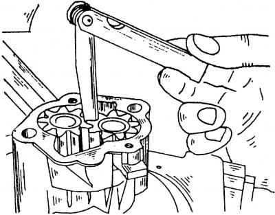
Pic. 171. Measurement of the backlash between the teeth of the gears of the oil pump
- measure with a feeler gauge (pic. 171) side clearance of the oil pump gears, which should be 0.05-0.20 mm. If it is exceeded, replace the gears or the entire pump;
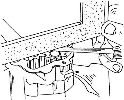
Pic. 172. Measurement of axial clearances of oil pump gears
- steel angle or steel ruler (pic. 172) measure the maximum axial clearance of the gears, which should be within 0.06-0.10 mm (for VR6 engine) or 0.05-0.15 mm (for 2.0 l engine). To measure the axial clearance, place a steel angle or steel ruler on the upper surface of the oil pump housing and use a feeler gauge to measure the distance between the ruler and the end surface of the gears;
- on the oil pump housing of the 2.0 liter engine, check the drive gear shaft for play. If it is, then it is best to replace the pump housing;
Note. Always replace gears in pairs if damaged or worn teeth are found. As a rule, wear marks on the flank of the teeth look like a polished shiny surface.
- clamp the pump cover (for VR6 engine) in a vice and unscrew the plug 13 (pic. 170) reducing valve. Remove spring 12 and valve flap 11 (the end of the damper trunnion sits inside and pay attention to this when assembling);
- check valve and spring. The pressure at which the valve must open is (550±20) kPa;
When assembling the oil pump, make sure that the contact surfaces of the parts of the pump housing are clean. Lubricate all parts with oil before assembly.
On the VR6 engine, insert bolts 8 from below (pic. 170) fixing the oil pump housing, wrap them and tighten to 25 Nm, and the bolts 4 inserted from above - to 10 Nm.
On the 2.0-liter engine, the mounting bolts 17 (pic. 166) tighten to 20 Nm.
Note. Before installing the pump, make sure the gears turn easily without binding.
Replace and lubricate both O-rings with engine oil 5 (pic. 170) pump drive shaft before inserting the shaft into the gear (VR6 engine).
Install a new gasket on the hole of the pump housing flange, install the oil receiver 2 together with the gasket 3 on the pump housing 7, screw in the new fastening bolts 1 and tighten them to a torque of 10 Nm.
Cover the oil receiver flange, which is attached to the crankcase, with sealant AMV 188 001 02 during assembly (VR6 engine). Lubricate the damper 11 of the pressure reducing valve with engine oil and insert it with a pin into the hole in the pump cover. Install spring 12 and screw cap 13.
Secure the pump in a vise and tighten the plug to 40 Nm (VR6 engine).
Visitor comments